Under-Cabinet LED Strip Planning Checklist for Cabinet and Joinery Teams
Translate cabinet drawings into a coordinated light-line, profile, wiring, control, cleaning and service-access brief.
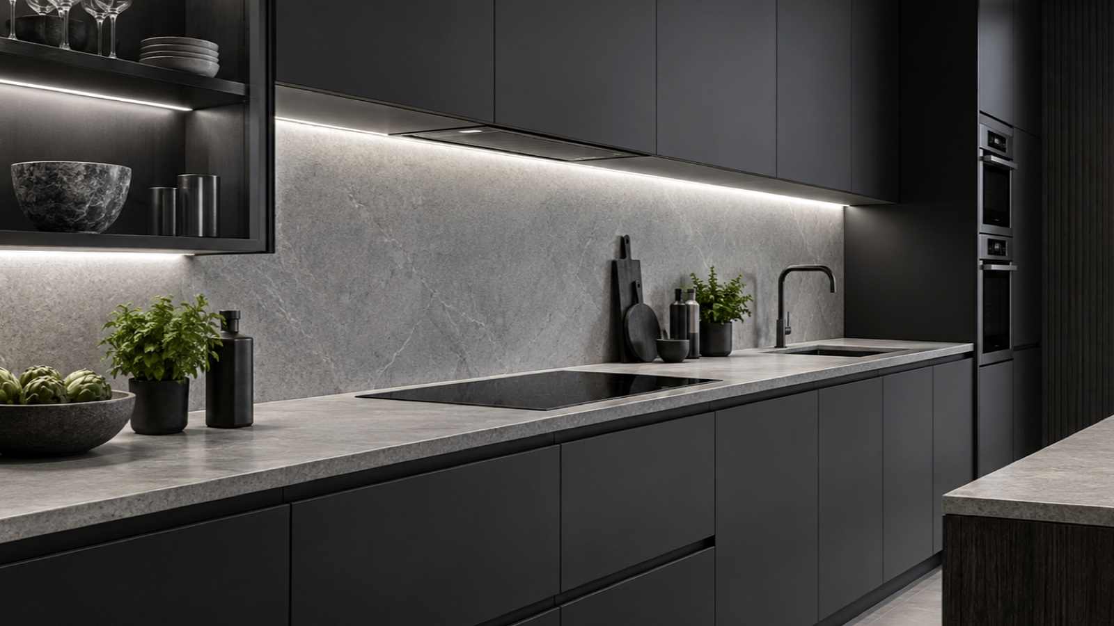
An under-cabinet LED strip specification should begin with the cabinet drawing, task surface and service route—not with a strip SKU. Define where light is needed, what the user can see, how the strip and profile fit the joinery, where cables and drivers can remain accessible, and how the team will approve a sample. These inputs turn a decorative idea into a buildable package for cabinet makers, joiners, kitchen designers and installers.
Mark the lighting task on the cabinet drawing
Start with a dimensioned plan, elevation and section. Mark every illuminated cabinet, shelf or recess as a separate run. Record breaks caused by appliances, sinks, corners, doors, structural panels and cable restrictions.
For each run, identify the task surface and the intended effect. A counter used for food preparation has a different visual task from a display shelf or toe-kick. Note whether the source, diffuser or reflection will be visible from standing, seated and nearby circulation positions.
The drawing should answer:
- where each light line starts and stops;
- which surfaces receive light;
- where direct view is possible;
- the available recess width and depth;
- how corners and cabinet breaks are crossed;
- where cables can pass between units;
- where drivers, controllers and connections remain accessible.
Use the kitchen and under-cabinet application page for application context and the cabinet and joinery planning page for manufacturing inputs. Neither page replaces the project drawing.
Position the light line for the task surface
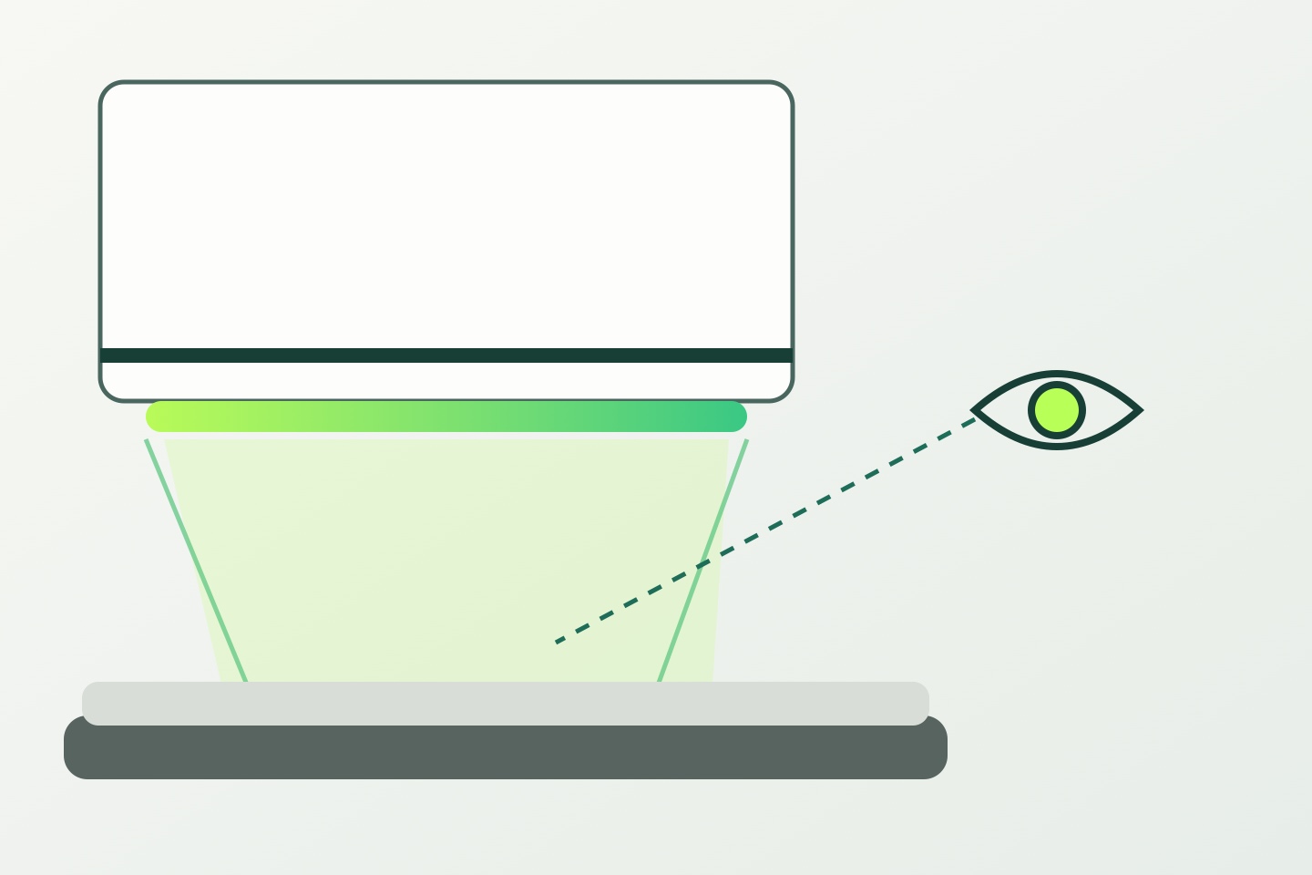
Placement changes both useful illumination and glare. A strip near the front of a wall cabinet can send more light toward the front of the worktop but may be easier to see from low angles. A strip farther back may change shadows and reflections. The right location depends on cabinet depth, user position, backsplash reflectance, profile optics and nearby surfaces.
Avoid a universal front or rear offset. Instead, show candidate locations on the section and review them with the real or representative profile, diffuser and surface finishes. Include the cabinet's front edge, any light rail, door swing and sightline.
For glossy counters, metal, glass or polished stone, look for reflected images of the light line as well as direct glare. A strip hidden from direct view can still appear clearly in a reflective surface.
Match the strip, profile and diffuser to the joinery
Treat the strip, profile and diffuser as one mechanical and optical assembly. Verify actual internal profile width, strip width and height, connector or solder-joint clearance, diffuser fit, end caps and cable exits. Published nominal dimensions are not a substitute for a tolerance review when the assembly must fit a routed recess.
| Fit question | Drawing or evidence needed | Approval point |
|---|---|---|
| Recess | Width, depth, corner radius and machining tolerance | Profile fits without forcing or visible gaps |
| Strip | Exact width, height, cut interval and pad layout | Strip fits with connection clearance |
| Diffuser | Material, finish, transmission and attachment method | Appearance accepted in the selected profile |
| Ends | End-cap and cable-exit dimensions | Cabinet end detail remains clean and serviceable |
| Joints | Solder or connector method and required space | Joint fits without lifting the diffuser |
| Mounting | Clips, adhesive or fasteners and substrate | Assembly remains secure and removable as planned |
Do not assume that a deeper profile or denser strip automatically produces a continuous light line. Visible point sources depend on the full geometry, materials, output and viewing conditions. Approve a representative sample.
Plan color, output and controls around the use case
Record the required white-light appearance, color-rendering criteria, dimming behavior and zone logic. Kitchen task lighting, display lighting and ambient toe-kick lighting may need different criteria even in the same room.
LED light quality is not captured by a single family label. The U.S. Department of Energy notes that LED products vary in energy efficiency and color qualities, and that fixture and power-supply design affect system performance.1 Compare exact product data and representative samples rather than relying on terms such as “natural white.”
Define how the light is switched or dimmed. If door sensors, occupancy controls, wall dimmers or a building system are involved, record the interface and default behavior. Separate control zones where users or operating schedules require independent action.
Route wiring and preserve driver access
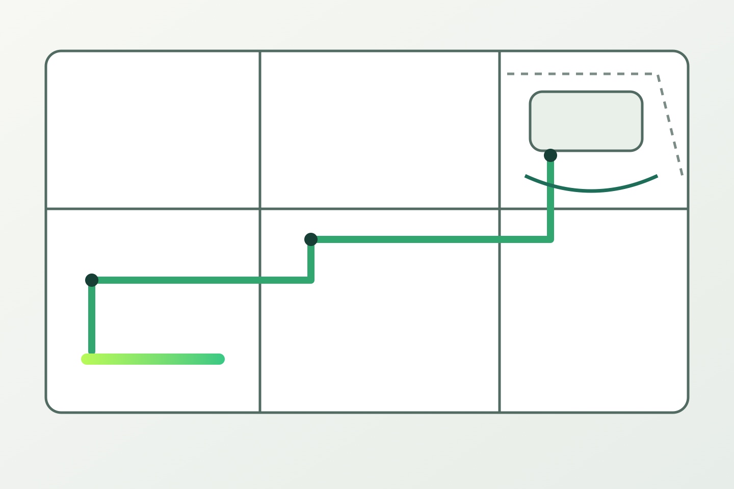
The cabinet package should show cable holes, concealed routes, transitions between cabinets, connector positions, driver location and isolation points. Coordinate these before fabrication so installation does not depend on drilling through finished panels without a plan.
Check:
- conductor capacity and route based on the reviewed electrical design;
- clearance from moving hinges, drawers and hardware;
- protection where cables pass through panels;
- access to drivers, controllers, terminals and branch connections;
- ventilation and environmental conditions for control equipment;
- a replacement path that does not require unnecessary cabinet damage.
Do not bury a driver or connection solely to keep it out of sight. Concealment and serviceability need to be resolved together.
Account for heat, cleaning and exposure
LED assemblies generate heat that must move through the circuit board and mounting system.2 Follow the selected strip and profile instructions and evaluate the cabinet material, enclosure, operating time and nearby heat sources. Do not state that a profile guarantees a particular temperature or lifetime without comparable evidence.
Record exposure to steam, splashes, grease, cleaning agents and abrasion. The complete installation includes cut ends, joints and cable entries, not only the strip body. In a kitchen or hospitality setting, cleaning access and material compatibility can be as important as the appearance on installation day.
Approve a representative sample before production
A useful sample reproduces the real section closely enough to answer the decision. Use the intended cabinet finish, profile, diffuser, strip candidate, mounting position and viewing condition. Drive the sample with compatible equipment and record the settings.
Review at least:
- light placement on the task surface;
- direct and reflected glare;
- visible points or dark transitions;
- color appearance on key materials;
- dimmed and full-use scenes where required;
- fit, cable exit and joint appearance;
- access for diffuser removal and strip replacement;
- cleaning of the finished detail.
Photographs can document the review, but fixed exposure and white balance are needed for a meaningful side-by-side comparison. Preserve the approved product and document revisions with the sample record.
Under-cabinet specification checklist
- Dimensioned plan, elevation and section identify every run.
- Task surfaces, direct-view angles and reflective surfaces are marked.
- Candidate placement is shown relative to the cabinet front and rear.
- Recess, profile, strip, diffuser and end-cap dimensions are verified.
- Cut intervals, joints, corners and cable exits are resolved.
- White-light, color-rendering and dimming criteria are stated.
- Zones, switches, sensors and default behavior are documented.
- Driver, controller and terminal locations remain accessible.
- Cable routes are coordinated with hardware and fabrication.
- Heat, cleaning and moisture conditions are reviewed.
- A representative sample has named acceptance criteria.
- Final drawings and approved revisions are retained for production.
Send the drawings and constraints
The most useful inquiry includes the cabinet drawings, finishes, profile or recess constraints, run schedule, task requirements, control method, driver location, sample criteria and unresolved questions.
Send the drawings and constraints for review. An inquiry does not confirm engineering approval, product fit, performance, availability, price, lead time or an order.
Sources
[1] U.S. Department of Energy, “LED Basics”. General system-performance and light-quality context; not a product claim. Accessed 2026-10-04.
[2] U.S. Department of Energy, “Thermal Management of White LEDs”. General thermal-path explanation; exact product instructions control. Accessed 2026-10-04.
Bring the comparison into a project brief.
Share the documented requirements and unresolved questions. An inquiry begins review; it does not confirm engineering approval, compatibility, stock, price, lead time, compliance or an order.
Prepare a project brief