LED Density, Diffusers and Profile Depth: Planning a Cleaner Light Line
Evaluate the complete strip–profile–diffuser assembly under a defined viewing condition instead of relying on density or format labels alone.
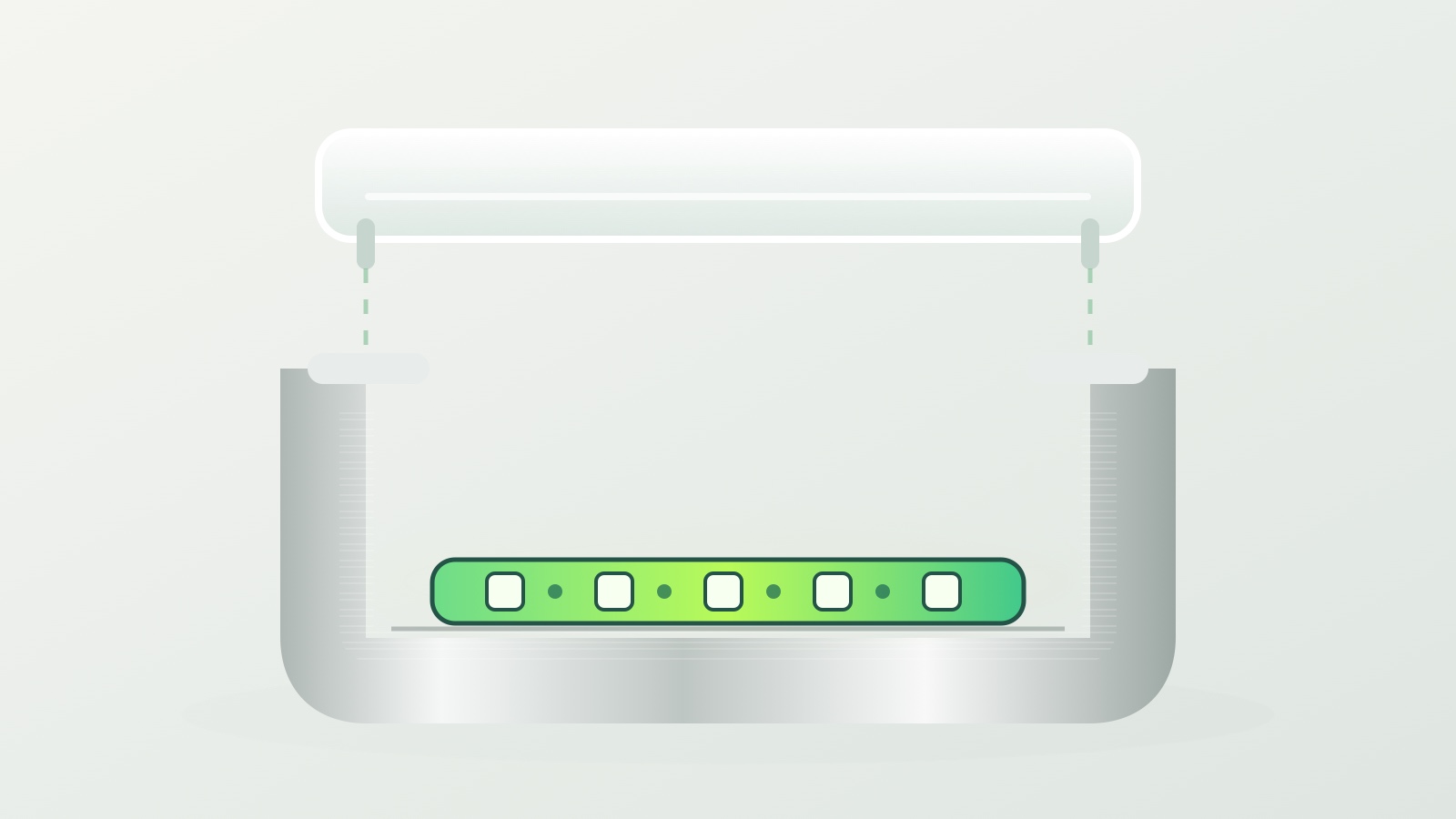
Visible LED points are not determined by LED density alone. The result depends on the spacing and emitting geometry of the exact strip, distance to the diffuser, profile shape, diffuser material, output level, viewing distance, surrounding surfaces and camera exposure. A reliable specification compares the complete strip–profile–diffuser assembly under representative conditions instead of promising a universally “dot-free” line.
Start with the viewing condition
Define who sees the light line and from where. A profile hidden in a cove is evaluated differently from one mounted at eye level inside a display. Record the shortest expected viewing distance, viewing angles, whether the diffuser is directly visible, ambient light and reflective surfaces.
If the installation will be photographed or filmed, add camera position, exposure and white balance. Cameras can reveal patterns differently from the human eye, so visual and recorded acceptance should be documented separately.
Write an observable criterion such as: “No distracting discrete points visible through the selected diffuser from the agreed review positions under the approved operating scene.” Avoid using “dotless” without a stated setup.
Understand LED pitch and emitting geometry
LED density describes a count per length, while pitch describes the spacing between emitting elements. Both can inform a comparison, but neither alone predicts the finished light line. Package size, emitting area, layout, phosphor construction and operating level also influence appearance.
Use exact model data. Do not infer pitch from a category name, and do not assume that COB and SMD labels guarantee a particular visual result. The existing COB LED strip family can support candidate discovery; it is not evidence of universal uniformity.
| Strip input | What to record | Why it matters |
|---|---|---|
| Model and revision | Exact identifier and source document | Keeps the comparison traceable |
| Emitting layout | Density, pitch or construction data available for the model | Describes the source pattern |
| Width and height | Actual dimensions and tolerances | Determines profile fit and diffuser distance |
| Cut interval | Segment length and pad position | Affects transitions and short details |
| Rated input | Voltage and verified power data | Defines the test condition |
| Color data | CCT, color metrics and tolerance where relevant | Prevents optical review from ignoring light quality |
Treat diffuser distance as a geometric variable
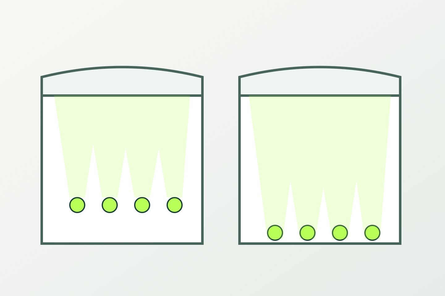
Increasing the distance between source and diffuser can change how light from adjacent emitters overlaps, but there is no universal minimum depth that works for every strip and diffuser. Profile internal geometry, sidewalls, reflector finish and the diffuser's optical properties also matter.
Measure the complete cross-section:
- internal profile width and depth;
- strip position within the profile;
- distance from the emitting surface to the diffuser;
- diffuser thickness, curvature and attachment;
- sidewall and base finish;
- any gap caused by clips, adhesive or connectors.
Review the profiles and diffusers category for published component families, then verify exact dimensions and fit. Do not design a routed recess from a category-page image.
Compare diffuser material and finish
Diffusers trade light transmission, scattering, surface appearance and mechanical properties. A more scattering diffuser may reduce visible points in one assembly while also changing delivered light and appearance. Clear, frosted and opal labels are not standardized performance values across every supplier.
Ask for the specific diffuser paired with the profile. Record material, finish, thickness, transmission data where available, color stability requirements, cleaning exposure and replacement access. Compare samples with the same strip, drive condition, profile and viewing setup.
LED system efficiency depends on both the light source and the wider fixture or optical design.1 Keep source efficacy, strip-level data, diffuser losses and delivered illumination separate when evaluating a candidate.
Include surface finish and surrounding geometry
The profile and nearby surfaces can reflect, absorb or reveal the light pattern. A glossy dark cabinet, pale matte cove and polished metal shelf may produce very different impressions with the same strip assembly.
Document:
- profile base and sidewall finish;
- surface color and reflectance around the light line;
- whether the source is direct, indirect or reflected;
- nearby edges that create bright or dark bands;
- recess alignment and tolerance;
- expected dust, cleaning and aging conditions.
Do not approve the illuminated line on a loose bench sample if the real installation relies on a reflective wall or narrow recess that is absent from the test.
Run a controlled side-by-side sample review
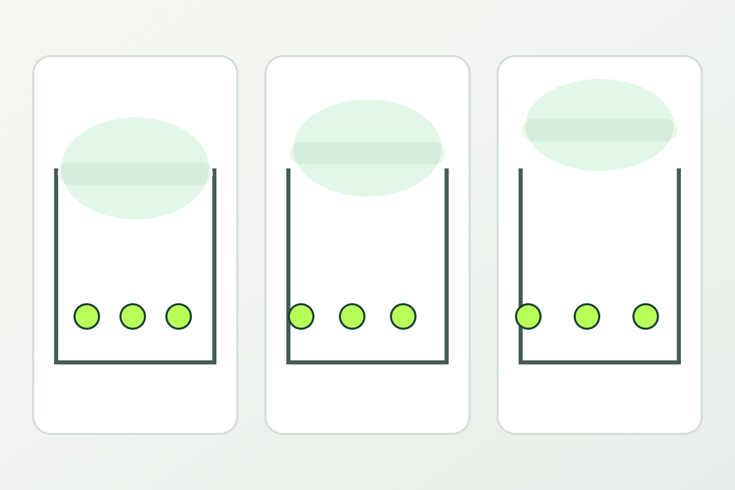
The sample review should change one meaningful variable at a time. If both strip and diffuser change together, the team cannot tell which caused the difference.
| Test field | Keep constant | Record as the variable |
|---|---|---|
| Strip comparison | Profile, diffuser, distance, drive and view | Exact strip model |
| Diffuser comparison | Strip, profile, drive and view | Exact diffuser |
| Depth comparison | Strip, diffuser, drive and view | Emitting-surface-to-diffuser distance |
| Output comparison | Strip, profile, diffuser and view | Documented operating level |
| Camera comparison | Physical setup and scene | Fixed exposure settings and lens position |
Preserve the sample identifiers, setup drawing, original photographs, reviewer, date, observations and decision. Separate measured values from visual preferences. An approved result applies to the named setup, not to every installation using the same marketing label.
Balance appearance with fit, heat and service
A deeper profile may be impossible inside thin joinery. A highly scattering diffuser may change output. A tight enclosure may change thermal conditions. A connector may fit the strip but lift the diffuser or create a visible transition. These tradeoffs need one coordinated decision.
LEDs produce heat that must move through the circuit board and assembly, so follow the exact strip and profile instructions.2 Do not infer lifetime or permissible operating temperature from the profile's material alone.
Service questions include how the diffuser is removed, whether the strip can be replaced without damaging the finish, where joints sit and how spare components are identified. A visually approved mockup that cannot be installed or serviced is not a complete specification.
Cleaner-light-line checklist
- Review positions and shortest viewing distance are defined.
- Direct, reflected and camera views are identified.
- Exact strip model and emitting layout are recorded.
- Profile internal dimensions and strip fit are verified.
- Emitting-surface-to-diffuser distance is measured.
- Exact diffuser material and finish are named.
- Surface colors, reflectance and recess geometry are represented.
- Drive condition and dimming state are controlled.
- Samples change one comparison variable at a time.
- Original photos and setup records are retained.
- Thermal, connector and service constraints are reviewed.
- Approval is limited to the named assembly and use condition.
Request a fit and sample review
Provide the section drawing, recess limits, viewing condition, candidate strip, profile and diffuser identifiers, operating scene, surface finishes and acceptance method. This lets the reviewer evaluate the assembly rather than a density number in isolation.
Request a fit and sample review. A sample request does not confirm stock, compatibility, performance, price, lead time, test approval or production acceptance.
Sources
[1] U.S. Department of Energy, “LED Basics”. General explanation that LED device and fixture design both affect system performance. Accessed 2026-10-04.
[2] U.S. Department of Energy, “Thermal Management of White LEDs”. General thermal-integration principles; exact product instructions take precedence. Accessed 2026-10-04.
Bring the comparison into a project brief.
Share the documented requirements and unresolved questions. An inquiry begins review; it does not confirm engineering approval, compatibility, stock, price, lead time, compliance or an order.
Prepare a project brief