Tunable-White LED Strip System Brief: Strip, Controller and Driver Inputs
Build a tunable-white request as one documented system: define the lighting task, then verify the exact strip, voltage, channel and interface, controller, driver load, zones, scene behavior and maintenance needs without assuming compatibility.

A tunable-white brief must identify the required CCT behavior and zones, then match one exact strip voltage and channel format with a controller interface and a driver sized from documented load. Similar voltage, connector shape or product-family wording does not prove compatibility.
A tunable white LED strip system brief turns a lighting intention into a reviewable system request. Use our RGB, RGBW and tunable-white selection guide if the light function itself is not yet decided. Once tunable white is selected, treat the strip, controller and driver as three separate components whose interfaces must be verified.
Define the CCT task, zones and operating periods
Begin with what each area must do. “Dimmable warm-to-cool light” is too broad for a supplier to evaluate zones, control inputs or operating behavior.
| Zone | Lighting task | Warm/cool behavior | Control point | Schedule | Override and restart behavior to specify |
|---|---|---|---|---|---|
| Reception | Welcome and general circulation | Define desired states or adjustment range | Wall control, remote, app or building system | Opening, normal operation, closing | Who may override; desired state after power returns |
| Dining or lounge | Ambience and task visibility | Define scene states; do not assume continuous tuning | Local or central control | Service periods and cleaning | Manual scene access and restart expectation |
| Corridor | Orientation and cleaning | State whether one fixed white or adjustable white is needed | Central schedule or local input | Day, night and cleaning periods | Safe manual control requirement |
| Guest or private area | User comfort | Define allowed user adjustment | Local wall or handheld control | Occupied and unoccupied periods | Default and limits to be agreed |
These rows are planning examples, not preset ULANTU scenes. For every real zone, provide the task, desired white-light behavior, independent control requirement, daily operating periods and any manual override. A CCT adjustable LED strip is useful only when the project has a defined reason to change white light; a fixed-white strip may be the clearer choice for zones that do not need it.
Also state whether the project requires a gradual transition or discrete scene states, whether zones must act together, and whether a wall control, remote, app or building-management interface is expected. Do not assume a protocol, CCT range, memory function or building-system compatibility without exact product documentation.
Select the exact strip voltage and channel format
Choose an exact strip before sizing its controller and driver. Record the product ID and SKU, not just “dual white.”
| Strip field | Required entry |
|---|---|
| Product and SKU | Exact identifier |
| Light function | Fixed white or tunable white as documented |
| Nominal voltage | Exact model value |
| Channel/conductor format | Only what the model documentation states |
| Documented W/m | Required for load calculation; do not infer it |
| PCB/finished width | Required for mounting and connectors |
| Installed length and branches | Record each zone separately |
| Cut interval | Exact SKU field |
| Protection construction | Strip-body construction and separate connection treatment |
| Connection interface | Lead, connector and conductor arrangement |
ULT-EDFD07E0 illustrates why configuration-level reading matters. V0049, V0050 and V0051 are listed as 8 mm, 120 LEDs/m dual-white configurations, but V0049 is a 12V plated-PCB version, V0050 is a 12V die-cut uncoated version, and V0051 is a 24V die-cut uncoated version. The shared family description does not establish the CCT endpoints, W/m, conductor format or controller interface for any of them.
Review the current tunable-white LED strip range by exact configuration. Lock the voltage and channel format before discussing control equipment.
Match the controller by channel, interface and user behavior
A tunable-white controller must match the selected load electrically and must provide the required user behavior. Compare controllers by documented fields rather than appearance.
| Controller field | Why it matters |
|---|---|
| Controlled load type and channel format | Establishes whether the output architecture matches the strip |
| Input and output voltage | Must match the system design |
| Rated output or current per channel | Limits the connected load under stated conditions |
| Output interface | Must match the selected conductor and connector arrangement |
| User input | Wall panel, buttons, remote, app or other documented input |
| Zone capability | Determines whether independent areas can be operated separately |
| Scene behavior | Defines what users can select and save, where documented |
| Restart and failure behavior | Must be checked for the real controller |
| Included accessories | Prevents a missing receiver, remote, lead or panel from being assumed |
ULT-DC1498D8 is a 5V USB cable-and-control family. V0012 through V0016 identify four-key tunable-white controls in specific colors and cable lengths, while V0020 identifies a 1 m tunable-white touch-control cable. These examples show that button type, cable length and color are SKU-level choices. They do not establish compatibility with the 12V or 24V strip examples above.
Compare controllers and use the controller channels and interface guide to document the required fields. A connector that looks similar is not evidence that channel order, voltage or load limits match.
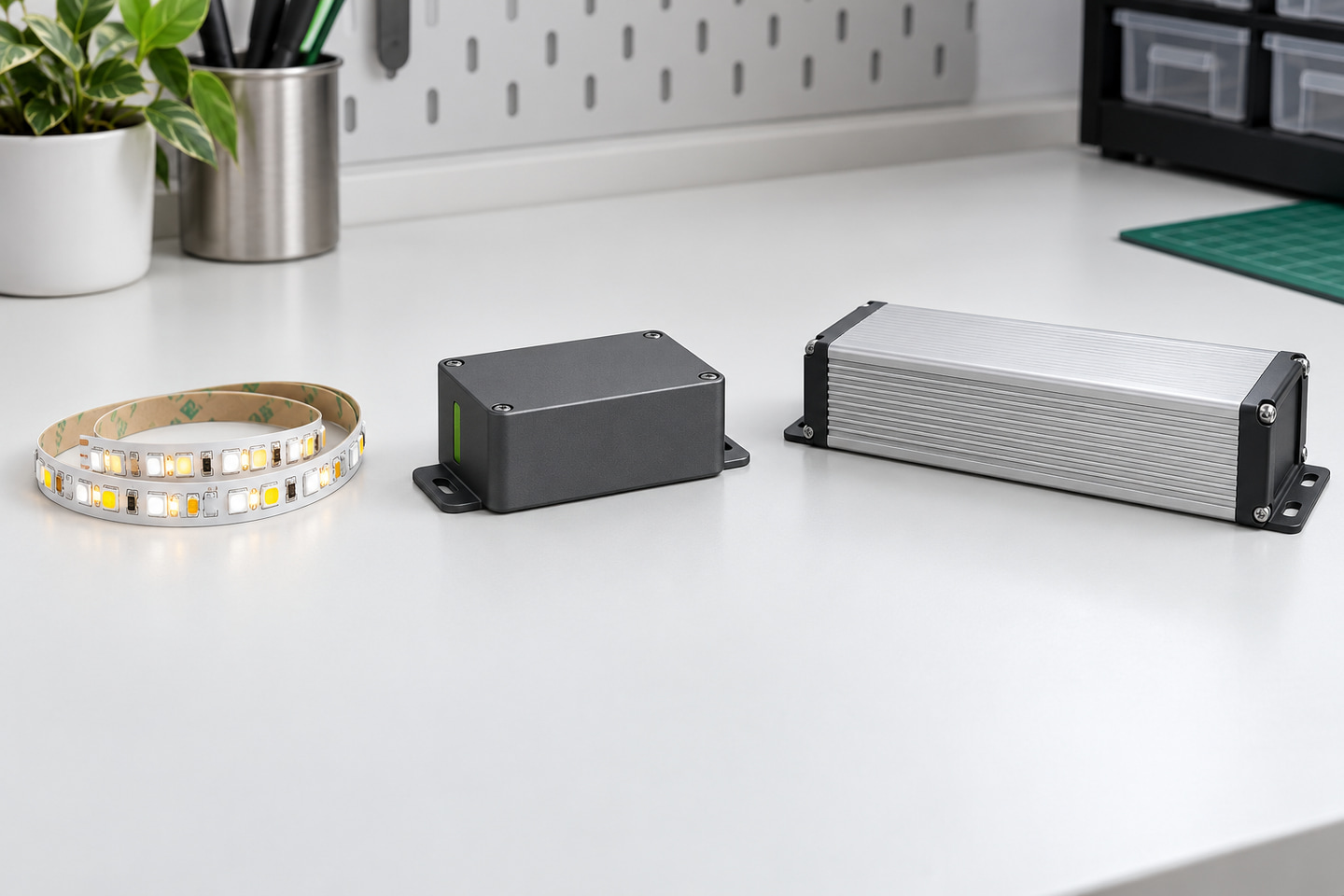
Size the driver and divide the electrical zones
Calculate each branch from the selected strip's documented load:
Branch power = documented W/m × installed metres
Then total the branches that one driver is intended to supply. Apply the driver manufacturer's loading, installation and derating requirements rather than a universal allowance. The Mean Well LED power-supply installation guidance, for example, directs users to the individual model specification for mounting, derating and dimming details (LED Driver Installation Manual). That general principle does not establish the requirements of an unrelated driver model.
| Electrical zone | Strip SKU | Voltage | W/m | Length | Calculated load | Driver candidate | Controller path | Feed points | Service isolation |
|---|---|---|---|---|---|---|---|---|---|
| Zone 1 | |||||||||
| Zone 2 | |||||||||
| Zone 3 |
ULT-AEAC5956 provides examples of driver fields, not a pre-approved system. V0001 and V0002 are listed as 12V, 150W and 200W configurations with a 2.4G panel/Bluetooth combination; V0003 and V0004 are 24V counterparts at 150W and 200W. The selected strip, controller, panel and driver still require a model-specific compatibility review.
Use LED drivers to identify candidates and our power-supply sizing and voltage-drop guide to prepare the branch inputs. Include supply location, cable route, feed points and maintenance isolation. Do not set a universal reserve percentage, cable size or maximum run without the actual load, equipment and installation conditions.

Document scenes, commissioning and maintenance needs
Tunable-white is a control function, not just a strip specification. The DALI Alliance, for example, describes tunable-white control as correlated-colour-temperature control along the warm-to-cool white path; it does not imply that the products in this article support DALI (DALI Colour Control). Your brief should name the control method that the project actually needs.
For each zone, document:
- zone name and physical boundary;
- authorized control points;
- desired scene states or adjustment behavior;
- minimum and maximum operating states required by the project;
- manual override requirement;
- expected state after a power interruption;
- controller and driver location;
- label and access method;
- settings or configuration files that should be handed over, without passwords;
- replacement component identity; and
- sample or mock-up checks required before approval.
Keep controllers and drivers accessible under the project maintenance plan. Record the exact model, settings version and zone assignment so a replacement does not rely on memory. These are procurement and handover inputs, not a claim that one standard commissioning process fits every site.
Send the strip-controller-driver brief
Complete one row for every independently controlled zone:
| System field | Zone input |
|---|---|
| Area and lighting task | |
| Required warm/cool behavior | |
| Exact strip product/SKU | |
| Length and branch layout | |
| Voltage and documented W/m | |
| Channel/conductor format | |
| Controller model or required interface | |
| Driver model, voltage and rating | |
| Feed points and cable route | |
| User control and scene behavior | |
| Restart/manual override requirement | |
| Controller/driver service location | |
| Sample or mock-up requirement | |
| Quantity and destination | |
| Required technical documents | |
| Compatibility points to verify |
Send each zone's task, exact strip SKU, length, voltage, documented W/m, channel/interface, controller and driver candidates, feed points, scenes, quantity, destination and document needs through Request a Tunable-White System Review.
Bring the comparison into a project brief.
Share the documented requirements and unresolved questions. An inquiry begins review; it does not confirm engineering approval, compatibility, stock, price, lead time, compliance or an order.
Prepare a project brief