How to Choose an LED Strip Controller by Channel, Interface and Use Case
Start with the strip channels and lighting task, then select the interface, zones and commissioning method for the complete control chain.
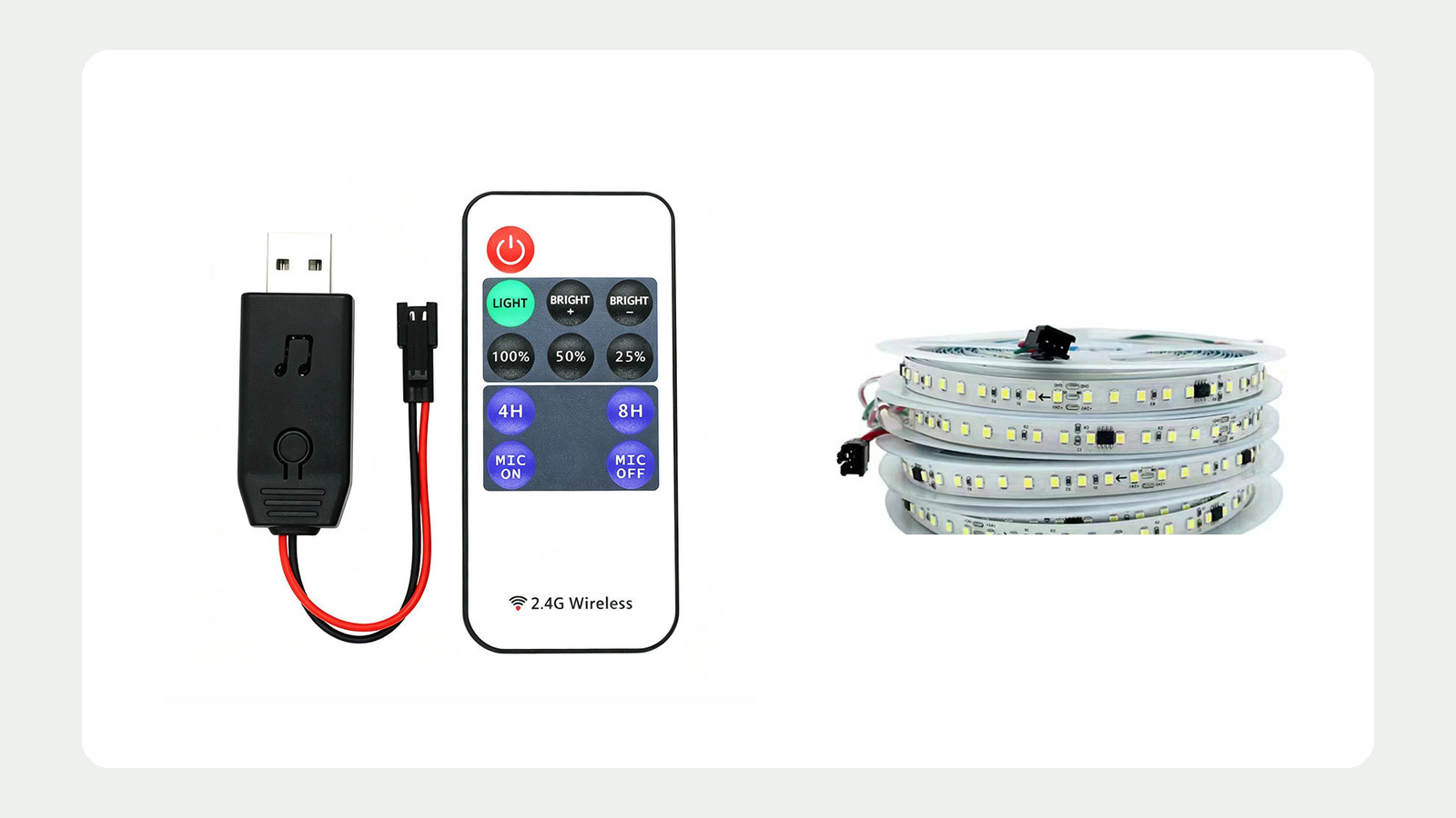
Choose an LED strip controller by working outward from the strip and the lighting task. First match the strip’s channel architecture and electrical requirements. Then define the user interface, zones, scenes, signal path, commissioning method and service plan. Choosing an app or remote first can produce a convenient interface attached to the wrong controller architecture.
Start with the strip channels
Record the exact strip type before comparing controllers. The controller must support the strip’s electrical architecture, not merely a similar marketing label.
| Strip task | Typical channel question | What the brief must confirm |
|---|---|---|
| One white-light output | Is this a single controlled channel? | Strip voltage, total branch load, dimming method and required low-end behavior |
| Tunable white | How are the warm and cool channels arranged? | Common conductor, channel order, supported CCT-control method and combined load |
| RGB | How are red, green and blue channels wired? | Common conductor, channel order, scene needs and color-mixing expectations |
| RGBW | Is the white channel separate from RGB? | Four-channel order, white-light task and scene behavior |
| Other multi-channel system | What does each pad and conductor do? | Exact strip drawing, controller output arrangement and protocol requirements |
Do not infer compatibility from connector shape, cable color or the words “RGBW” and “CCT” alone. Obtain the strip and controller connection diagrams and create a channel map.
The controller collection is the current route for candidate discovery. It does not mean that every listed controller supports every strip, load or interface.
Define the interface from the user’s task
The interface is how a person or building system operates the controller. It should be chosen from the use case, not from novelty.
Ask who will operate the lighting and what they need to do:
- switch one zone or several zones;
- dim to a repeatable level;
- adjust white color temperature;
- recall color or effect scenes;
- schedule operation;
- hand over control to staff, guests or a facilities team;
- restore a known state after power loss;
- operate the system if a phone, account or network is unavailable.
Then compare interface options.
| Interface | Useful when | Questions before selection |
|---|---|---|
| Wall or furniture control | A fixed, obvious control point is required | Wiring, location, scene labels, lockout and replacement |
| Handheld RF control | Local wireless operation is acceptable | Pairing, range in the real space, zoning and spare-controller procedure |
| Touch panel | Several functions need a fixed interface | Supported channels, scene logic, supply and commissioning |
| App control | Authorized users need portable configuration or operation | Platform support, account dependence, permissions, update policy and offline behavior |
| Building-control interface | Lighting belongs to a wider controls project | Exact protocol, gateway, addressing, commissioning owner and documentation |
For example, DALI color control distinguishes control types including tunable-white and RGB-family functions under IEC 62386 Part 209. That standard context does not make a generic multi-channel controller a DALI device; certification and supported color types must be checked for the exact product.1
Check electrical fit at controller and branch level
Document these values for every controlled zone:
- strip rated voltage;
- verified power or current basis for the installed length;
- number of output channels;
- load per channel and total connected load;
- controller input and output limits;
- driver or power-supply arrangement;
- conductor lengths, feed points and voltage-drop plan;
- required protection, isolation and enclosure conditions.
A controller’s total rating may not be available to every channel in every operating condition. Check per-channel and total limits, derating, ambient temperature and installation instructions for the exact model. Do not use an unreviewed “headroom percentage” as a substitute for those instructions.
If amplifiers, repeaters or multiple power supplies are proposed, draw the complete signal and power paths. Define common references, synchronization, isolation and startup behavior according to the actual equipment instructions.
Plan zones before choosing the remote
A zone is a separately controlled lighting group. A scene is a saved or commanded state across one or more zones. Keep those concepts separate.
Create a zone schedule:
| Zone | Lighting task | Strip/channel type | Control point | Scenes or states | Failure/service impact |
|---|---|---|---|---|---|
| Record project zone | State the task | Record exact architecture | Name interface | List required states | State what becomes unavailable |
Use one zone only when the lights genuinely share the same schedule, level, color behavior and service boundary. Splitting every short run into its own zone can make commissioning needlessly complex; combining unrelated spaces can make operation confusing.
For each scene, describe the intended result instead of using names alone. “Retail evening” should specify which zones operate and what is adjusted. Exact output values remain subject to commissioning and approved products.
Document pairing, addressing and recovery
Wireless and addressed systems need a commissioning record. Without it, replacing a controller or user device can turn a small service task into a full recommissioning exercise.
The record should include:
- controller model and location;
- zone and device names;
- pairing or addressing method;
- authorized configuration devices or accounts;
- firmware or application requirements where relevant;
- saved scene list;
- power-loss and reset behavior;
- backup and restore method if supported;
- replacement and re-pairing procedure.
Do not publish passwords, private account details or security credentials in a general handover sheet. Store sensitive commissioning information through the project’s controlled process.
Review interoperability as a complete chain
The controller sits between other components. Check the whole chain:
User interface → gateway or receiver → controller → strip channels → power system
A shared protocol name does not prove every feature is supported. Verify the commands, channel types, scenes, feedback and commissioning functions the project actually needs.
Use the controls and dimming category to see the current product-family context. If documents are needed for a candidate device, use the technical document request and identify the exact model and document type.
Test the user journey, not only the output
A representative test should confirm both electrical operation and the intended user experience.
Run these scenarios:
- first power-up and normal restart;
- switching and dimming from every authorized interface;
- color or CCT adjustment where applicable;
- scene recall across all assigned zones;
- loss and restoration of wireless or network connection;
- replacement or reset of one device;
- simultaneous commands from multiple controls;
- operation at the expected minimum and maximum connected load;
- handover to a person who did not configure the system.
Record unexpected states, latency, pairing limits and recovery steps. Do not convert a demonstration into a general compatibility claim.
Controller-selection checklist
- Exact strip model, rated voltage and channel order are documented.
- Controller output architecture matches the strip architecture.
- Per-channel and total loads are within documented limits.
- Driver, controller and strip power paths are shown.
- User roles and required interfaces are defined.
- Zones and scenes are scheduled before equipment selection.
- Protocol, gateway and interoperability requirements are explicit.
- Pairing, addressing and recovery records are planned.
- Power-loss, offline and reset behavior have been tested.
- Control equipment remains accessible for service.
- The approved sample names every tested component and configuration.
When the strip architecture, load schedule, interface and zones are defined, Request a Control-System Review. Include the strip and controller candidates, wiring diagram, zone schedule, required scenes, user interfaces and commissioning constraints. Review is required before treating any combination as compatible.
Sources
[1] Digital Illumination Interface Alliance, “DALI Colour Control”. Official overview of DALI color types and IEC 62386 Part 209 context; exact certification and feature support remain product-specific. Accessed 2026-10-05.
Bring the comparison into a project brief.
Share the documented requirements and unresolved questions. An inquiry begins review; it does not confirm engineering approval, compatibility, stock, price, lead time, compliance or an order.
Prepare a project brief