SMD LED Strip Specification: 2835, 5050, Density and Project Inputs
Define the lighting task first, then compare exact 2835 or 5050 products by configuration, density, board width, electrical requirements, light function and installation conditions before building a sample shortlist.
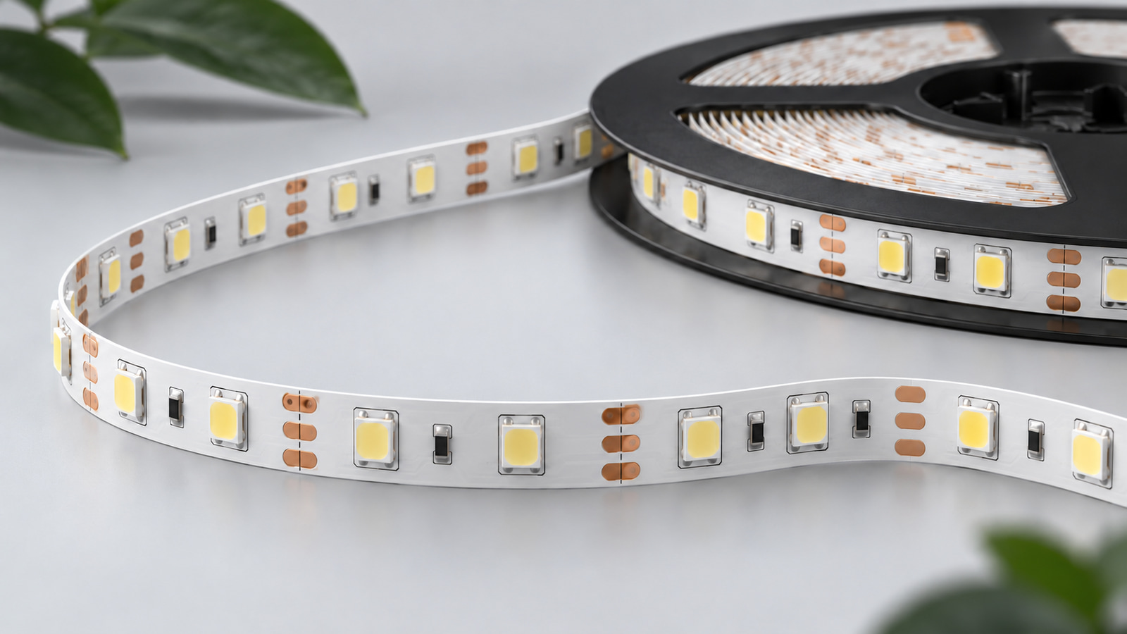
Do not shortlist an SMD strip from the package number alone. Define the lighting task and viewing condition, then compare exact SKUs by density, width, voltage, power, color or control function, protection, cut and feed layout, and the profile or mounting space. Approve the selected configuration in its real installation condition. A useful SMD LED strip specification keeps all of those fields together.
If the project has not yet selected between package formats, use the COB vs SMD project comparison first. Once SMD is selected, the current SMD LED strip range is the product-discovery route; this guide explains how to turn the project into a model-level shortlist.
Define the lighting task and viewing conditions
Begin with what the light must do and how it will be seen. A white task-light strip inside an aluminum profile, a reflected accent line and a color-changing kit do not become comparable simply because two products use 2835 or 5050 packages.
| Project input | What to state before selecting a package |
|---|---|
| Task or effect | Task light, accent, reflected light, decorative color or product integration |
| View | Direct, reflected or through a diffuser |
| Viewing condition | Closest and typical distance, angle and surrounding surface |
| Light function | Fixed white, fixed color, adjustable white or RGB requirement |
| Environment | Dry indoor, damp, splash-prone or exposed condition |
| Mounting | Surface, recess, profile or built-in product location |
| Available space | Clear width, depth, bend route and connection clearance |
| Service access | How the strip, controller and power equipment will be reached |
| Control need | Simple switching, dimming, color control or another defined behavior |
Write the project input before naming a package
Describe the desired result without turning it into an unsupported package rule. For example, write “fixed 3000K white light viewed through the specified diffuser at the normal viewing distance,” not “must be 2835 because 2835 is brighter.” Write “5V RGB kit with the quoted controller behavior,” not “5050 means RGB.”
The project input should let a supplier reject unsuitable candidates before samples are shipped. It should also state any non-negotiable system condition, such as an existing voltage, a fixed profile size or the need to match a current control interface.
Compare the exact 2835 and 5050 product options
The package number is one specification field. Voltage, LED density, light function, supplied format, control equipment and protection still belong to the exact variant.
| Product and SKU | Package | Voltage | Density | Light function | Supplied format and relevant configuration |
|---|---|---|---|---|---|
| ULT-BC30171E-V0001 | 2835 | 12V | 120 LEDs/m | 6500K white | 5 m reel format; non-waterproof bare-board family; reference price basis per metre |
ULT-BC30171E-V0004 | 2835 | 24V | 120 LEDs/m | 3000K white | 10 m reel format; non-waterproof bare-board family; reference price basis per metre |
ULT-BC30171E-V0007 | 2835 | 12V | 60 LEDs/m | 6500K white | 5 m reel format; non-waterproof bare-board family; reference price basis per metre |
| ULT-B33FEDE4-V0001 | 5050 | 5V | 12 LEDs/m | RGB | 1 m, uncoated, single-run kit with 20-key music-responsive IR controller and foil bag |
ULT-B33FEDE4-V0009 | 5050 | 5V | 12 LEDs/m | RGB | 30 m total supplied as two 15 m reels using a 1-to-2 output; not one continuous 30 m strip |
Treat the package number as one field, not the verdict
These examples show why a 2835 LED strip is not one universal white-light configuration and a 5050 LED strip is not automatically an RGB kit. The three 2835 variants differ in voltage, density, CCT or reel format. The 5050 examples are specific 5V RGB kit configurations; they do not establish the behavior of every 5050 product.
Do not infer power, brightness, quality, board width, cut interval or protection from the package number or from a photo. Keep any undocumented value as a supplier question tied to the exact candidate SKU.
Evaluate LED density with board width and optical geometry
LED density matters, but its effect must be evaluated with the complete light path. Board or finished width determines whether the strip fits. Profile depth, diffuser transmission, strip-to-diffuser distance, viewing angle and surrounding reflectance influence whether individual points remain visible. Power and optical output are separate documented fields.
| Review field | What to compare in the sample |
|---|---|
| LEDs per metre | Verified density for the exact SKU |
| Package spacing | Calculate only from a verified density when the calculation is useful |
| Board or finished width | Documented dimension matched to clear installation space |
| Profile geometry | Internal width, depth and strip position |
| Diffuser | Actual finish and transmission condition used by the project |
| Strip-to-diffuser distance | The installed distance, not a generic threshold |
| Viewing condition | Distance, angle and direct or reflected view |
| Surface reflectance | Color and gloss of the receiving surface |
| Observed result | Line continuity, visible points, glare and fit under the stated condition |
Check the complete light path in a sample
Change one variable at a time when comparing candidates. Put each strip in the intended profile, use the same diffuser and power condition, and view it from the same position. Record what changes rather than declaring one density universally better.
For example, ULT-BC30171E-V0001 and V0007 are both listed as 12V, 2835 and 6500K, but one is 120 LEDs/m and the other 60 LEDs/m. That supports a controlled density comparison for those exact candidates; it does not prove a universal brightness or “dotless” ranking. The LED density, diffuser and profile-depth guide explains how to structure the geometry review.
Do not transfer the 5 cm cut interval shown for a documented 24V structure to every SKU in the family. Verify the marked or documented cut interval for the exact sample being considered.
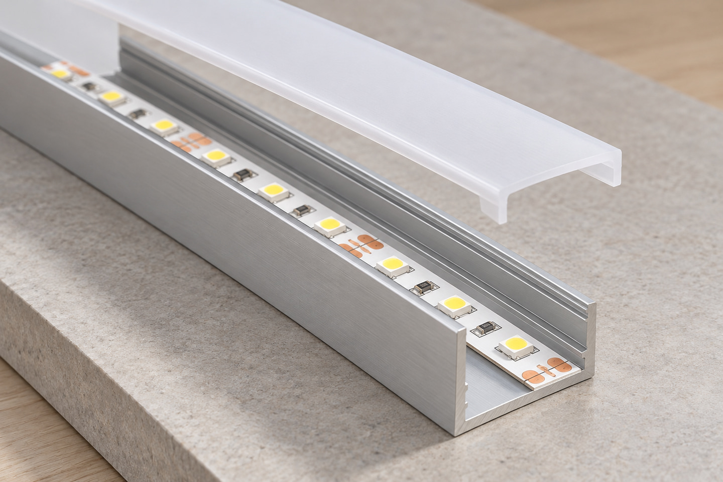
Specify voltage, power, control and environment
An SMD shortlist is incomplete until the electrical chain and installation environment are clear. A voltage label must match the power source and controller; the listed W/m and branch length are needed before sizing power; and the strip, joints and power equipment each need protection appropriate to their locations.
| System field | Required project or model input |
|---|---|
| Exact voltage | Candidate SKU voltage and planned system voltage |
| Listed power | W/m or other stated basis for the exact SKU, if documented |
| Connected length | Length per feed branch, not only the total order quantity |
| Power source | Planned compatible supply and installation location |
| Control chain | Controller channels, interface and load relationship for the selected strip |
| Feed plan | Feed points, branches and any required injection arrangement |
| Cut and leads | Exact cut interval, lead direction and connection clearance |
| Protection | Strip, cut ends, joints, controller and power equipment considered separately |
| Mounting and heat path | Surface or profile, ventilation and service access to be reviewed |
Review the whole electrical and installation chain
Use this sequence:
- Lock the system voltage and reject variants that do not match it.
- Obtain the exact SKU power basis and map connected length by branch.
- Confirm that the controller’s channels, interface and capacity match the selected light function.
- Identify exposure at the strip, every joint and the power/control equipment.
- Check cut positions, feed locations, connector direction and service access in the sample layout.
USB describes a power connection form; it does not establish an addressable protocol or compatibility with an unrelated controller. Likewise, a controller supplied with one 5V RGB kit should not be applied to a different channel or interface without model-level evidence. Use the controller-selection guide for channel and interface questions, and the power-supply sizing and voltage-drop guide once the exact power and branch data are available.
Do not create a universal safe run length, wire size, reserve percentage or wiring guarantee from the package number. Those decisions depend on the documented product, load, branch layout and applicable installation requirements.
Shortlist exact models and prepare the sample specification
Give every candidate its own row. A shortlist should show why the product remains under consideration, which fields are verified and what the sample must resolve.
| Shortlist field | Candidate entry |
|---|---|
| Product and variant ID | |
| Why shortlisted | |
| Package and verified density | |
| Voltage and documented power | |
| Board or finished width | |
| Color, CCT or RGB function | |
| Controller or accessory configuration | |
| Strip and connection protection | |
| Cut, feed and planned branch layout | |
| Sample length and quantity | |
| Intended profile, diffuser or surface | |
| Viewing and observation condition | |
| Open model-specific fields | |
| Volume quantity and destination | |
| Sample result and exact approved SKU |
Compare one complete configuration per row
Review samples in a repeatable order:
- Match the label, product ID and variant ID to the shortlist.
- Check the documented dimensions, density, cut marks and supplied format.
- Connect the sample only through the planned compatible power and control chain.
- Fit it into the intended profile, diffuser or mounting position.
- Observe every candidate under the same distance, angle, ambient condition and surface finish.
- Record fit, visible light pattern, control behavior and any difference from the quoted row.
- Approve only the exact configuration reviewed, including its reel or kit composition.
This is a buyer comparison method, not a ULANTU test result or quality ranking. Price, stock, MOQ, lead time, documents and sample availability depend on the current candidate and request.
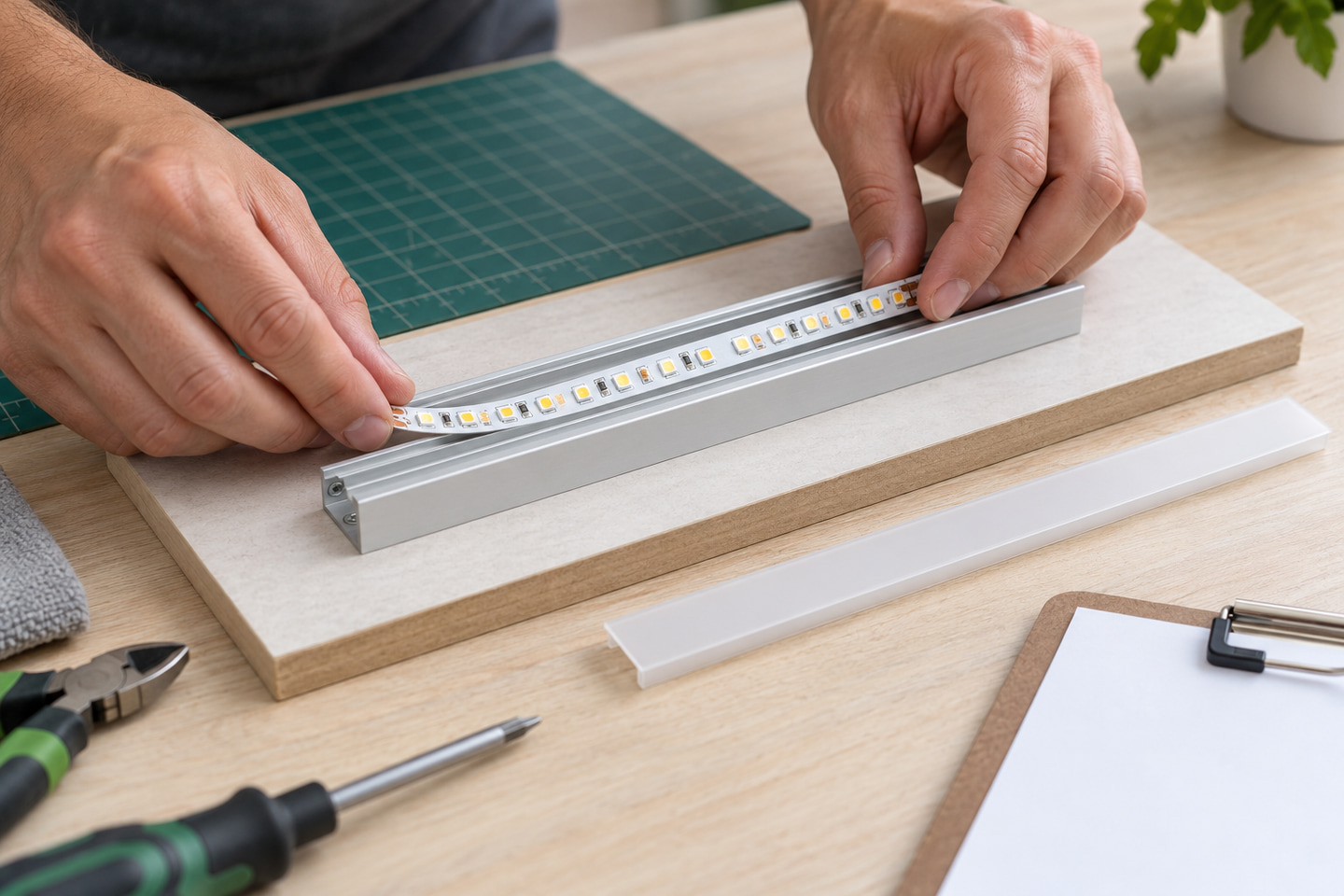
Send the lighting task, viewing and installation conditions, preferred package or current candidate, voltage, density and width requirements, color or control function, protection, sample quantity, total quantity and destination through Request an SMD Shortlist.
Bring the comparison into a project brief.
Share the documented requirements and unresolved questions. An inquiry begins review; it does not confirm engineering approval, compatibility, stock, price, lead time, compliance or an order.
Prepare a project brief