Signage Lighting Brief: Form, Environment, Wiring and Service Access
Define sign construction, optical depth, exposure, system protection, power, segmentation and service access before requesting a quote or sample.

Define the sign construction before selecting a strip, module, or flexible neon product. A useful signage lighting inquiry identifies whether the project is a channel letter, lightbox, or illuminated contour; then supplies the sign depth, face and diffuser materials, light-source position, environment, mounting orientation, cable and power routes, segmentation, service access, quantity, and destination market.
This signage LED lighting specification checklist helps sign makers and brand-project contractors prepare information that can be quoted and sampled. Explore our signage lighting options for your project. This guide addresses the technical brief rather than promising that one general LED strip for signs fits every construction.
Identify the sign construction before choosing a light source
Begin with dimensioned drawings of the completed sign. Include a front view, side or return detail, section through the illuminated area, mounting surface, and the planned access point. Mark which surfaces emit light and which remain opaque.
Record:
- sign type and whether it is face-lit, halo-lit, edge-lit, internally illuminated, or an exposed contour;
- overall dimensions, stroke widths, returns, corners, cavities, and separators;
- face, return, back, diffuser, reflector, and mounting materials;
- indoor, sheltered outdoor, or exposed outdoor location;
- installed orientation and expected water direction;
- available input power, equipment location, control task, and cable entry;
- factory-built and field-completed portions;
- removable faces, access panels, and replaceable parts;
- quantity, destination market, required documents, and sample stage.
Do not choose a generic light source from the front elevation alone. A shallow letter, deep cabinet, narrow contour, and edge-lit panel create different optical, thermal, wiring, and maintenance constraints.
Compare channel letters, lightboxes, and outline signs
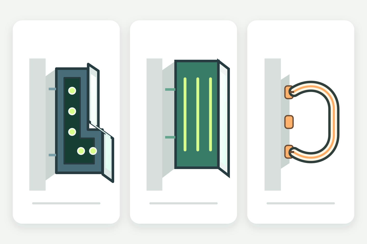
| Sign construction | Main lighting task | Information required before selection | Sample priority |
|---|---|---|---|
| Channel letter | Fill a defined letter cavity or create a controlled halo | Stroke width, return depth, face and back materials, module or strip mounting plane, wire passages, letter segmentation, and access method | Tightest stroke, smallest enclosed area, sharpest corner, and any halo offset |
| Lightbox | Illuminate a larger face with acceptable uniformity | Cabinet depth, face material and transmission, internal reflectance, structural shadows, source layout, ventilation, service opening, and face-removal method | Shallowest or largest representative bay, structural obstruction, and normal viewing distance |
| Outline or contour | Keep a luminous line aligned through curves and joints | Drawn centerline, visible light direction, candidate section, bend plane, mounting detail, segment ends, feeds, joints, and service route | Tightest documented curve, most visible termination, and hardest mounting transition |
For flexible neon signage, verify the exact candidate’s section, luminous face, permitted bend direction, minimum radius, cut conditions, mounting, and feed arrangement from model documentation and a representative route sample. See our LED neon flex bend direction, section size and mounting guide for selection details, and explore the LED neon flex collection for product options. Bend radius and output depend on the model.
Define depth, diffusion, source position, and uniformity
Uniformity results from the complete optical geometry. Sign depth, source spacing and aiming, face transmission, diffuser behavior, internal reflectance, structural shadows, and viewing distance interact. A spacing value from another sign should not be copied without confirming those conditions.
Prepare a section that shows:
- clear depth from the mounting plane to the illuminated face;
- light-source position and orientation;
- face, diffuser, light guide, reflector, and adhesive layers;
- internal ribs, fasteners, cables, or power equipment that can cast shadows;
- stroke width or illuminated-face width;
- normal and close viewing distances;
- removable parts and the tool path required to reach the light source.
Ask the supplier to identify the exact candidate and the basis for its proposed layout. Then evaluate a representative sample with the intended face material and depth. Photograph it with fixed camera settings if records are needed, but use the real viewing condition for acceptance.
For channel letters, include the smallest enclosed area as well as a typical letter. For a lightbox, include a joint or structural member if it may create a shadow. For a contour, include the tightest permitted curve and a real termination. The objective is to expose the hardest condition before bulk production.
Describe exposure and whole-system protection
State the environment in practical terms: indoor or outdoor, sheltered or directly exposed, horizontal or vertical orientation, rain or wash direction, dust, salt or chemical exposure, expected temperature range, sunlight, condensation risk, and cleaning method.
IEC 60529 classifies degrees of protection provided by enclosures.1 An IP rating on a light source therefore does not establish that the completed sign has the same protection. Review the scope of evidence for each boundary:
- light-source body or module;
- factory-prepared and field-prepared ends;
- connectors, splices, and cable entries;
- sign face, returns, back, seams, and drainage;
- driver, controller, and junction enclosures;
- mounting penetrations and field wiring;
- installed orientation and service openings.
Define water paths and drainage separately from component labels. Avoid pockets that retain water around cable entries or electrical equipment. If a removable face or access panel is part of the protective boundary, document its gasket, fasteners, closing sequence, and post-service inspection requirement according to the completed-sign design.
Certification and installation requirements also depend on the destination market and sign construction. UL Solutions, for example, identifies separate standards for electric signs, sign components, and LED sign or retrofit kits, and its sign program distinguishes dry, damp, and wet locations.2 Do not extend one component certificate to the completed sign or to a market outside its documented scope.
Map power, controls, cables, and segments
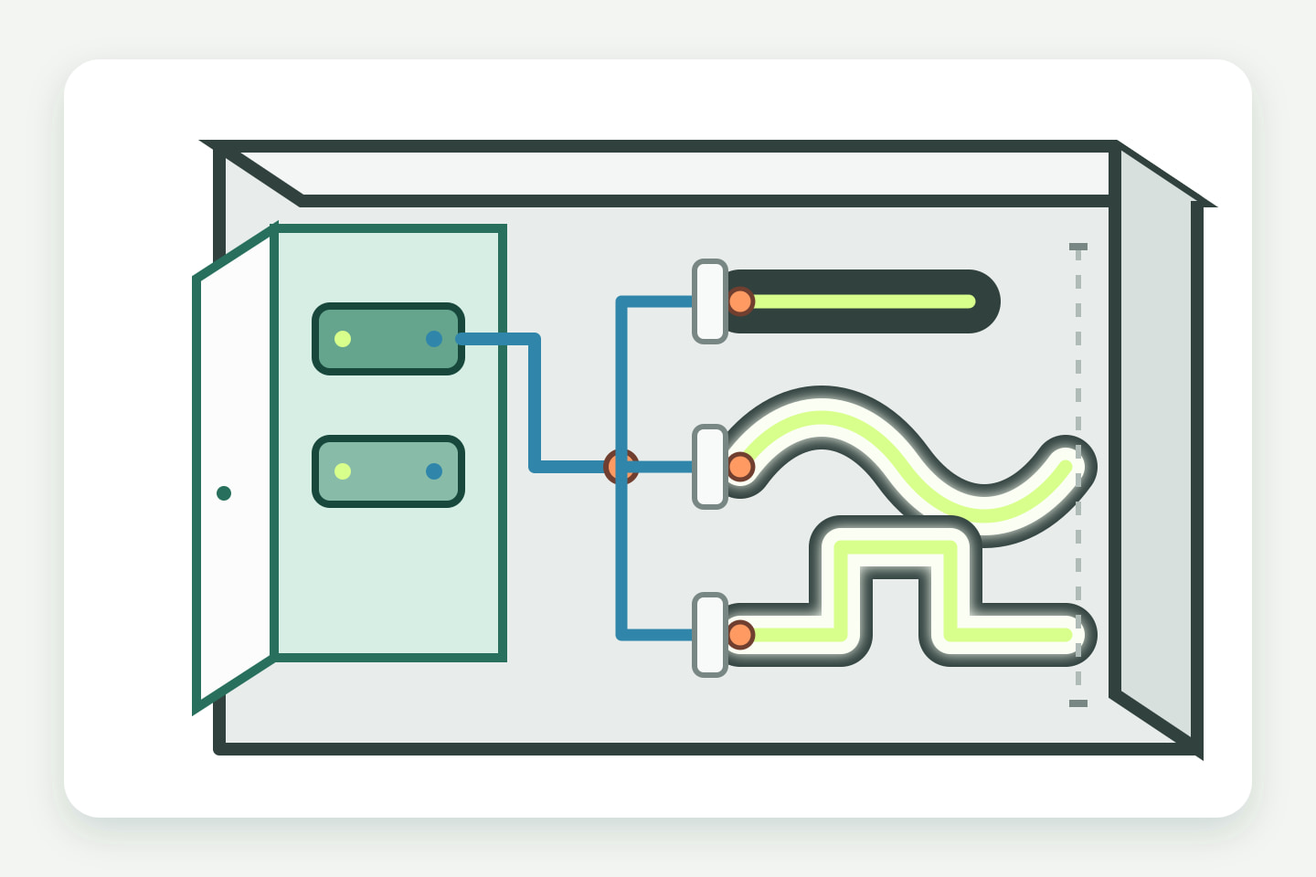
Create a one-line system diagram and a segment schedule before finalizing the source layout. The diagram should show the input, protective and switching equipment required by the project design, power supplies or drivers, controllers, distribution points, lighting segments, and accessible isolation or disconnection method.
The segment schedule should be practical enough for quotation and fabrication:
| Segment field | What to record |
|---|---|
| Drawing reference | Letter, lightbox bay, contour, or elevation identifier |
| Geometry | Illuminated length or area, depth, stroke width, curves, and obstacles |
| Candidate source | Exact model or open candidate status; never a generic family claim |
| Feed and connection | Feed location, connection type, cable exit, and field or factory preparation |
| Power/control zone | Associated driver or supply, controller, switching task, and zone name |
| Routed cable | Route, approximate length, conductor identification, penetrations, and restraint |
| Service access | Removable face or panel, access direction, tool clearance, and replaceable unit |
| Verification | Drawing review, representative sample, electrical checks, and required documents |
Do not calculate the electrical design from illuminated length alone. Use exact candidate documentation for rated input, load, permitted segment conditions, control method, cable requirements, and compatible equipment. Record whether a joint is factory-prepared or made during sign assembly, because that changes the process and inspection boundary.
Keep power equipment away from locations that cannot be reached after installation. If a large sign is divided into sections for transport, show the field connections and identification between sections. If several letters share equipment, define how faults are isolated and how each branch is traced during service.
Design service access and replacement
Every sign needs an explicit service boundary, even when a component is not intended for routine field replacement. Decide which assembly is replaced: one module, one light-source segment, one complete letter, one lightbox bay, one driver, or another documented unit.
For each serviceable part, record:
- the access panel, removable face, or rear opening;
- fasteners, gasket, clips, adhesives, and finishes disturbed during access;
- required tool clearance and safe handling plan established by the project team;
- connector or terminal identification;
- cable slack and strain-relief method;
- replacement-part identity and revision control;
- steps needed to restore seals, drainage, mounting, and electrical boundaries;
- inspection and functional checks after reassembly.
A replaceable LED component does not make the sign serviceable when the face is permanently bonded over it or when the driver is trapped behind the mounting surface. Test the intended access sequence on the sample and record it in the manufacturing or installation instructions.
Complete the signage project inquiry checklist
- Sign type, lighting method, and emitting surfaces are identified.
- Front, side, section, mounting, and service-access drawings share one revision.
- Overall dimensions, stroke widths, return depth, cavity depth, curves, and obstacles are shown.
- Face, diffuser, reflector, return, back, and mounting materials are specified.
- Normal viewing distance and the required visual result are described.
- Indoor or outdoor exposure, orientation, water direction, cleaning, temperature, dust, sunlight, and chemical conditions are stated.
- Factory and field preparation boundaries are marked.
- Ends, joins, splices, cable entries, penetrations, seals, and drainage paths are detailed.
- Input power, lighting branches, driver or supply locations, controls, zones, and cable routes are drawn.
- Segment schedule and field-connection identification are complete.
- Removable parts, access direction, replacement unit, and reassembly checks are defined.
- Quantity, destination market, installation responsibility, and required documents are stated.
- Representative sample construction and approval criteria are agreed before bulk production.
Approve a representative sample
Select the most demanding repeatable condition, not only the easiest straight section. Build it with the intended face or diffuser, cavity depth, source mounting, wiring, power and control equipment, connection preparation, seals, drainage detail, and service opening.
Review:
- appearance from the intended and close viewing distances;
- visible bright or dark areas, edge effects, structural shadows, joins, and terminations;
- color and control behavior required by the project;
- source retention, cable restraint, connector identification, and equipment mounting;
- access to drivers, controllers, connections, and replaceable lighting sections;
- restoration of faces, gaskets, fasteners, drainage, and other protective boundaries after service;
- documentation for the exact sample configuration and destination market.
Approval applies only to the recorded configuration. A change in sign depth, face material, source model, layout, driver, controller, connection, enclosure, or installed orientation can require renewed review. This is a sample-confirmation method, not a universal spacing rule, safety guarantee, or ULANTU performance test.
Send the drawings and project requirements
When the sign structure and system schedule are ready, Send Sign Drawings. Provide the dimensions, structural drawings, installation environment, quantity, and destination market. If the current form does not accept attachments, submit the project requirements first and use the existing ULANTU email channel supplied during follow-up to exchange the drawing files. Do not treat the inquiry submission as engineering approval, compliance confirmation, stock confirmation, or an order.
Sources
[1] International Electrotechnical Commission, “IEC 60529: Degrees of protection provided by enclosures (IP Code)”. Supports limiting an IP claim to the assessed enclosure boundary; it does not prove protection for field joints or the completed sign. Accessed 2026-10-11.
[2] UL Solutions, “Electric Sign Certification and Sign Component Solutions”. Supports separating sign, component, and LED sign/retrofit-kit standards and identifying the installation location and destination-market requirements; it does not establish certification for an unspecified ULANTU product or project. Accessed 2026-10-11.
Bring the comparison into a project brief.
Share the documented requirements and unresolved questions. An inquiry begins review; it does not confirm engineering approval, compatibility, stock, price, lead time, compliance or an order.
Prepare a project brief