LED Neon Flex Selection: Bend Direction, Section Size and Mounting Inputs
Trace the luminous path first, then verify the candidate’s bending plane, section, mounting envelope, feeds and environmental boundaries.

Select LED neon flex from the drawn light path. The path determines the required bending plane; the available recess and visible section determine the allowable product cross-section; the mounting, feed direction and environment then narrow the candidate further. “Top bend” and “side bend” are useful category labels, but the exact model drawing controls.
Trace the illuminated path before choosing a product
Draw the centerline of the intended luminous surface. Show every straight segment, curve, corner, end, feed point, expansion joint and interruption. Add the expected viewing direction so the illuminated face remains clear.
For signage, include letter strokes, returns, crossings and tight transitions. For architectural lines, include facade joints, wall changes, soffits, handrails or other construction that interrupts the route.
Use the drawing to answer:
- Does the path curve in the plane of the illuminated face or perpendicular to it?
- Are any compound or twisting movements required?
- Which curves are gradual, and which are tight or abrupt?
- Where can separate sections or cable links be hidden?
- Which ends and feeds will remain visible?
- Can the installed line be supported continuously or at the required intervals?
Do not force one neon-flex section to reproduce geometry outside its documented bending plane. Redraw impossible transitions as separate sections, approved joints or a different construction.
Confirm bend direction using the exact cross-section
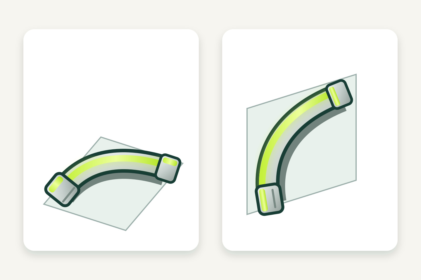
“Top bend” and “side bend” describe how a particular section is intended to curve relative to its luminous face. Naming conventions and section orientations can differ. Confirm the bending plane from the manufacturer’s drawing and a labeled sample.
A reliable drawing check uses three views:
| View | What to mark | Decision supported |
|---|---|---|
| Front or elevation | Visible light path and curve direction | Shows the intended graphic or architectural line |
| Plan | Recess, wall offset, mounting channel and cable exits | Shows lateral clearances and mounting access |
| Section | Illuminated face, product width/height and permitted bend plane | Confirms orientation and fit |
Mark “luminous face” and “permitted bending plane” directly on the sample-review drawing. Do not rely on the product name without that visual check.
The current LED neon flex collection is the starting route for candidate discovery. Exact bend direction, section and limits must be verified by model.
Match the section size to the construction detail
Record the complete product section, not only the visible luminous width. Include clips, channels, end caps, cable exits, tolerances and installation space.
Review:
- finished recess width and depth;
- clearance to insert the product without twisting it;
- channel or clip dimensions and fastener access;
- illuminated-face position relative to the finished surface;
- end-cap and side- or rear-feed clearance;
- drainage or water-management details where relevant;
- access to remove a section without damaging adjacent finishes.
A narrow visible line does not prove a narrow installation envelope. Connections and end treatments often govern the required space.
Use model-specific bend limits
Do not publish or approve a generic minimum bend radius. The permitted radius, bending plane, cut length and prohibited actions depend on the exact construction.
For each candidate, obtain and record:
- permitted bending direction;
- minimum radius stated for that model;
- whether bending is measured at the inner, outer or center reference;
- prohibited twisting, folding or repeated flexing;
- permitted cut points and end preparation;
- maximum single-feed or run conditions where documented;
- installation-temperature and ambient limits where applicable.
Transfer these limits to the path drawing. Identify every curve that approaches the model limit and include it in the physical mockup.
Plan mounting as part of the route
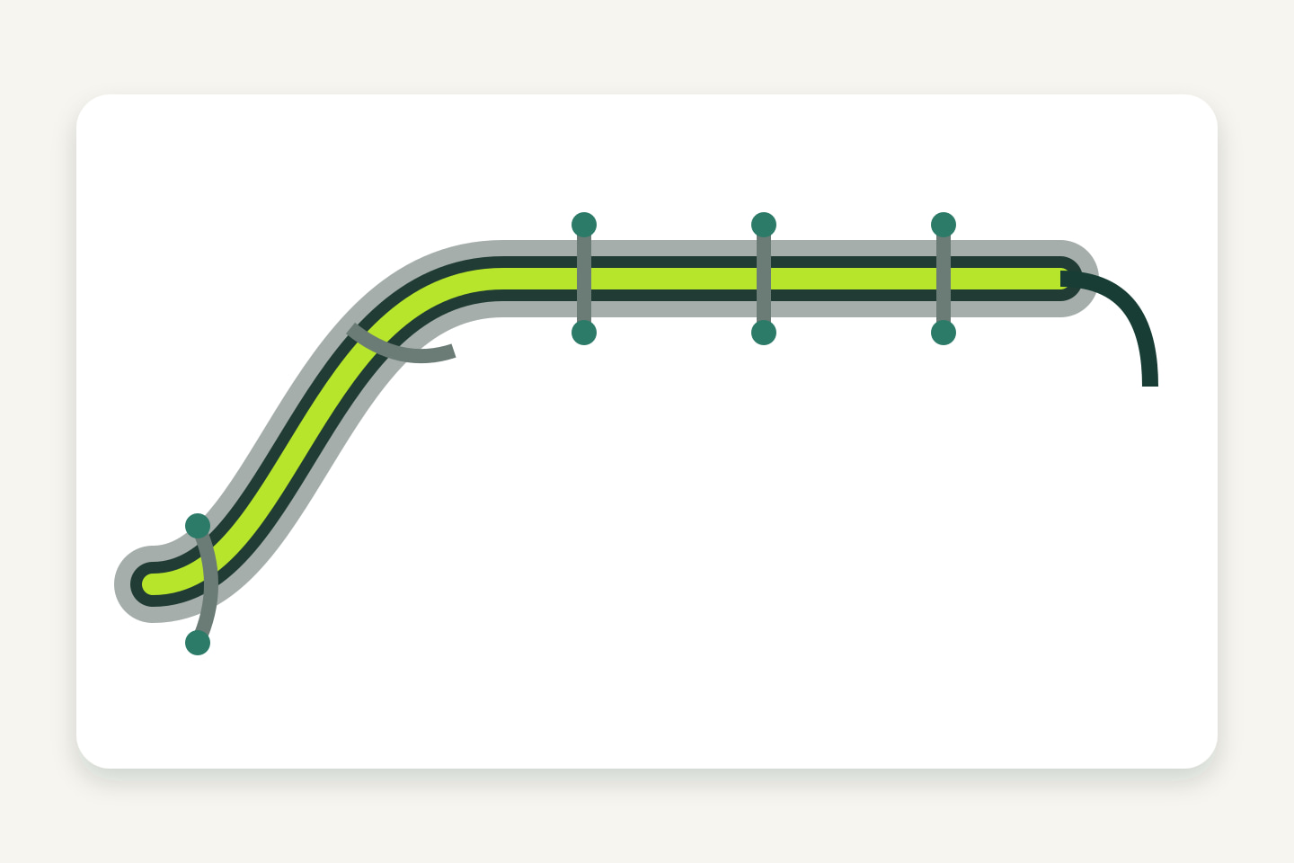
Mounting controls the line, orientation and mechanical load. It should hold the neon flex in its permitted plane without sharp local pressure or unsupported sagging.
| Mounting input | What to define |
|---|---|
| Substrate | Material, flatness, strength, finish and drilling restrictions |
| Support | Continuous channel, clips or another documented method |
| Fixing | Fastener type, spacing and edge clearances according to the selected system |
| Curves | How the support follows the permitted bend without forcing the section |
| Joints | Gaps, alignment and treatment at construction or expansion joints |
| Removal | How a section can be released for service |
Do not use adhesives, clips or channels that are not approved for the exact product merely because the section appears to fit. Check material compatibility, retention and environmental limits.
Coordinate feeds, cuts and control zones
Show every feed direction and cable route. End-feed, side-feed and rear-feed arrangements can change the visible termination and required recess space.
Prepare a segment schedule:
| Segment | Path length | Candidate section | Bend direction | Feed location | Mounting | Control zone |
|---|---|---|---|---|---|---|
| Record drawing reference | Measure from current drawing | Record model/section | Record from exact drawing | Mark on plan/section | Record system | Record zone |
The schedule supports quotation and sample planning, but measured path length is not automatically order length. Cut increments, end preparation, lead exits, factory assembly and installation allowances must be confirmed for the exact candidate.
If several sections share a control zone, document power and voltage-drop checks separately. Do not solve electrical limits by changing the mechanical route without coordinating the drawing.
Check the operating environment
Describe the environment in project terms: indoor or outdoor, sheltered or exposed, expected water direction, temperature range, cleaning method, UV exposure, dust, salt or chemical exposure, and access for maintenance.
Then verify the scope of evidence for the complete assembly:
- neon-flex body;
- factory and field-cut ends;
- cable entries and joints;
- mounting system;
- driver and controller enclosures;
- drainage and water paths;
- installation orientation.
An enclosure rating on the neon-flex body does not establish the rating of a field-prepared end or the entire installation. Keep component and assembled-system claims separate.
The signage lighting guide is the current application route for sign projects. Use it to organize viewing, maintenance and operating-condition inputs before requesting review.
Mock up the hardest part of the path
Choose the section with the tightest approved curve, most visible termination or most difficult mounting access. Use the intended substrate, channel or clips, end treatment and feed direction.
Review:
- the product follows the path without twisting or local deformation;
- the luminous face remains correctly oriented;
- curves look continuous from the normal viewing distance;
- end caps and cables fit inside the construction detail;
- mounting does not create visible pinching or unevenness;
- the section can be installed and removed without excessive force;
- the selected control and power arrangement operates the sample as intended.
Document the exact sample configuration. A mockup of one section or bend direction does not approve a different section.
Neon-flex path checklist
- The luminous centerline and viewing direction are drawn.
- Every curve is classified by plane and approximate radius.
- Exact candidate cross-section and luminous face are marked.
- Bend direction and minimum radius come from model documentation.
- No part of the path requires twisting or an undocumented compound bend.
- Recess, channel, clip, fastener and end-clearance requirements are shown.
- Cuts, sections, feeds, cables and control zones are scheduled.
- Environment is described for the complete assembly.
- Field ends and joints have a defined preparation and protection method.
- Driver, controller and isolation access are preserved.
- The hardest route condition has been mocked up and recorded.
When the path drawing and installation section are ready, Send a Neon-Flex Path Brief. Include the centerline drawing, views and sections, curve radii, desired luminous face, mounting substrate, feed constraints, environment, control zones and service access. Candidate selection remains subject to exact model drawings and a representative sample.
Sources
[1] International Electrotechnical Commission, “IEC 60529: Degrees of protection provided by enclosures (IP Code)”, edition 2.0 with amendments. Used to keep enclosure-protection scope separate from unverified whole-installation claims. Accessed 2026-10-05.
Bring the comparison into a project brief.
Share the documented requirements and unresolved questions. An inquiry begins review; it does not confirm engineering approval, compatibility, stock, price, lead time, compliance or an order.
Prepare a project brief