Motion-Sensor LED Lighting: Choosing the Trigger, Placement and Control Behavior
For cabinet teams, installers and buyers, this guide starts with the action that should turn the light on, then compares trigger principles, placement, control behavior and sample checks before choosing a sensor-based lighting configuration.

Choose the trigger from the action you need: movement in a defined area, a door changing position, or an intentional hand gesture. Then check where the sensor can sit, what could block or falsely activate it, how the light should turn off, and which power and control components the selected product actually includes. Confirm the behavior with a sample in the intended location. This motion-sensor LED lighting selection guide starts with behavior, not a shared “sensor” label.
Define the action before naming the sensor
Two lights may both switch on automatically but respond to different events. A person approaching an open wardrobe is not the same event as a cabinet door opening. An intentional hand action is different again. Write the required on-and-off sequence before comparing hardware.
Write an on-and-off sequence
Complete one row for every use area:
| Step | Buyer-defined behavior |
|---|---|
| Starting condition | Is the light off, at a previous setting, or manually controlled? |
| Trigger action | What exactly should the user or door do? |
| Switch-on result | Which light or zone should turn on, and at what documented setting? |
| Stay-on condition | Should continued activity keep it on, or is another behavior required? |
| Switch-off condition | No detected activity, door closed, a second gesture, or manual action? |
| Manual override | Is an override required, and how should normal automatic behavior resume? |
| Power interruption | What should happen after power is removed and restored? |
For example, “a person walks toward an open wardrobe and the light turns on” is a motion-trigger requirement. “The light follows the door’s open or closed position” is a door-state requirement. “The user moves a hand near a defined point” is an intentional proximity or gesture requirement. These are planning examples, not claims that every function is available in a ULANTU product.
Compare motion, door and gesture triggers
Select the principle that matches the user action. Similar lighting outcomes do not make sensors, controllers, connections, or mounting conditions interchangeable.
Choose by user action, not a shared label
| Trigger principle | Intended action | Suitable planning context | Likely obstruction or unintended activation | Model-specific evidence to request |
|---|---|---|---|---|
| Passive infrared (PIR) motion | A person moves through the sensor’s detection field | Open wardrobes, circulation areas, or furniture where approach movement is the desired event | Door panels, stored items, lens direction, heat changes, airflow, or unrelated movement can affect behavior | Exact sensor/lens information, mounting orientation, documented modes, power, load, connectors, and sample behavior |
| Door-position sensing | A door changes between defined positions | Cabinets where light should follow door state rather than nearby movement | Sensor-to-target alignment, door travel, mounting tolerance, and surrounding magnetic material where relevant | Exact sensing principle, counterpart/magnet requirements if applicable, switching logic, mounting gaps, wiring, and sample behavior |
| Intentional hand/proximity input | A hand approaches or passes a defined control point | Mirrors, counters, or furniture where deliberate touch-free control is required | Surface material, installation depth, nearby objects, moisture, and accidental hand movement | Exact sensing technology, permitted cover material/thickness, calibration or setup, control behavior, and sample behavior |
PIR sensors receive changes in infrared energy rather than emitting a tracking beam. Panasonic explains that PIR detection depends on changing infrared intensity and that a lens shapes the detection area; the same FAQ notes that objects other than people can be detected when the change is sufficient. See the Panasonic PaPIRs operating-principle FAQ. This supports a general design caution, not a distance or sensitivity claim for a ULANTU model.
Door-state sensing is a different problem. Texas Instruments describes magnetic position sensing as detecting changes in a magnetic field caused by a target’s movement, which can be used for position states. See the TI magnetic position-sensing application brief. Exact door hardware and logic still depend on the chosen product.
“Gesture” is also not one universal technology. Microchip’s capacitive proximity design guide shows one possible approach to touch-free proximity input, but a marketing label alone does not prove that a device uses capacitive sensing. Request the candidate’s actual technical record.
ULANTU’s current public motion-sensor products provide motion-trigger examples. Door-control and gesture-control rows above are general sourcing comparisons, not statements that ULANTU currently supplies those configurations. Compare published motion-sensor LED strip configurations by exact product and SKU.

Place the sensor where it can detect the intended action
Sensor placement is part of the control specification. A suitable trigger can still perform poorly if its view is blocked, aimed at unrelated movement, exposed to unsuitable environmental changes, or installed where it cannot be serviced.
Check field, obstruction and false triggers
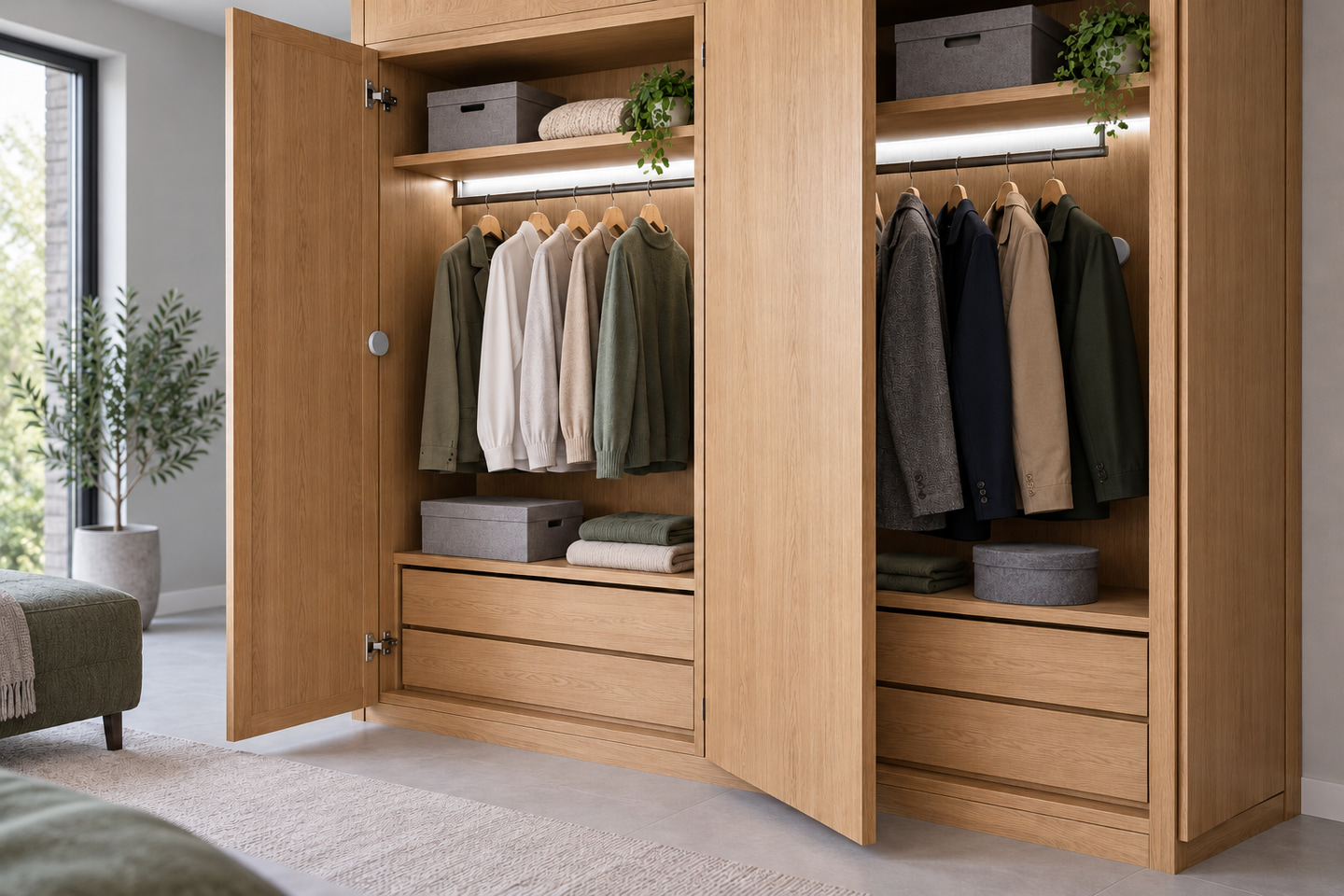
Consider two common conditions. In an open cabinet near a walkway, a sensor aimed into the room may respond to passing traffic that has nothing to do with using the cabinet. In a deep wardrobe, a door edge, shelf, or hanging clothing may block the intended approach. The correct position is the one that detects the desired action while limiting irrelevant activity in that specific setting.
Use this placement sequence:
- Mark the user action and direction of travel on the furniture drawing.
- Mark the candidate sensor position and its documented observation direction.
- Check the line of sight through every door position and normal storage condition.
- Identify passing people, pets, moving curtains, cleaning activity, sunlight, heat sources, and strong airflow that may affect the location.
- Keep the sensor and connections accessible for adjustment, inspection, or replacement.
- Test the representative sample in normal daytime, nighttime, open-door, closed-door, and occupied conditions relevant to the project.
Panasonic advises evaluating PIR products in the actual equipment and describes how obstacles and ambient conditions can affect detection. TI’s PIR false-trigger reference design likewise treats lens, field of view, installation, and environmental interference as system-design factors. These sources support the need for placement testing; they do not establish a universal range, angle, or false-trigger rate for the products discussed here.
Do not specify one detection distance for every location. Ask for the exact model documentation, then verify the intended action and likely false triggers with the actual enclosure, furniture, and sample.
Specify switch-off, override and power behavior
The trigger only describes how an event is detected. The controller and power arrangement determine what the light does next. Record switch-off logic, any required override, input supply, load, and whether the chosen item is a controller or a complete lighting kit.
Ask for the exact controller record
| Selection field | What to record or verify |
|---|---|
| Product and exact SKU | Product ID, variant ID, and complete option label |
| Trigger type | Documented sensing principle for that SKU |
| Input supply | Battery box, USB, adapter, or another documented input |
| Product scope | Controller only, sensor plus lead, or complete strip kit |
| Switch-off condition | Documented fixed behavior or buyer-required behavior to verify |
| Timeout setting | Record only if the selected model documents it |
| Manual override | Record only if the selected model documents it |
| Load and connector | Required strip voltage, connection format, and documented load boundary |
| Included parts | Strip, sensor/controller, power item, mounting items, and any excluded items |
The distinctions are practical:
- ULT-C2004F5A is a 5V COB motion-sensor strip-kit family. Its listed configurations include the strip, USB interface, and sensor box. Four AAA batteries are not included, and battery power and external USB power must not be used at the same time.
- ULT-5DFB664E is a controller family, not automatically a complete LED strip kit. Its V0001 option is a four-AAA battery box and the batteries are not included. Other controller options must be evaluated by their exact option record.
- ULT-C0F2E382 is a 12V COB motion-sensor strip kit offered in listed lengths and white/warm-white choices. The adapter plug depends on the selected option; for example, V0001 is a white 1 m kit with an EU plug.
- ULT-6094F1B2 includes both sensor-component and complete strip-set configurations. The buyer must identify which scope the selected SKU represents and match the 5V USB supply, connector, and strip format.
Compare standalone motion-sensor controller options separately from complete strip kits. Do not infer adjustable delay, manual override, charging time, battery life, range, or cross-product compatibility unless the selected model’s approved record states it.
Test a sample in the actual furniture or room context
A representative sample should answer the project’s action sequence in the real setting. A bench demonstration cannot reveal every obstruction, passing movement, door position, or service constraint.
Record results before ordering
Use the same candidate SKU and installation conditions intended for the order, then record:
- exact product and variant ID, sample date, and sample photos;
- sensor height, orientation, recess or surface position, and surrounding material;
- the intended approach, door, or hand action and whether it switches the correct zone;
- normal triggers and any unwanted triggers during representative use;
- switch-off behavior after the intended activity stops;
- behavior after power is disconnected and restored;
- performance with the door, shelf contents, clothing, and other likely obstructions in place;
- accessibility for the user, installer, and maintenance team;
- cable, power unit, controller, and connector access; and
- differences between the sample condition and other planned installation locations.
One sample result supports only the tested product, position, environment, and behavior. Repeat the check when a meaningful condition changes.
For furniture sections, profiles, wiring routes, and service access beyond the trigger decision, use the wardrobe lighting installation planning guide. The wardrobe and furniture lighting application provides the relevant commercial application route. This article remains focused on trigger choice, placement, and control behavior.
Send a sensor-use brief
Copy this table into your project request:
| Brief field | Buyer input |
|---|---|
| Furniture, room, or product application | |
| Drawing, dimensions, or photos available | |
| Action that should switch the light on | |
| Condition that should keep it on | |
| Condition that should switch it off | |
| Required manual override, if any | |
| Number of zones | |
| Candidate product and exact SKU | |
| Required power input | |
| Controller-only or complete-kit scope | |
| Proposed sensor location and orientation | |
| Likely obstructions or unrelated movement | |
| Strip/load and connector requirements | |
| Quantity and destination | |
| Required model-specific documents | |
| Sample evaluation questions |
Submit the intended action, drawings or photos, proposed sensor position, candidate SKU, power and product-scope requirement, desired switch-off behavior, quantity, destination, and sample questions through Submit a Sensor-Use Brief. A project review should identify what the selected product documents and what must be confirmed with the representative sample; it should not assume a universal sensing distance or behavior.
Bring the comparison into a project brief.
Share the documented requirements and unresolved questions. An inquiry begins review; it does not confirm engineering approval, compatibility, stock, price, lead time, compliance or an order.
Prepare a project brief