Wardrobe LED Lighting: Planning Sensors, Profiles and Service Access
Coordinate activation behavior, profile placement, furniture clearances, wiring zones and service access before wardrobe production begins.
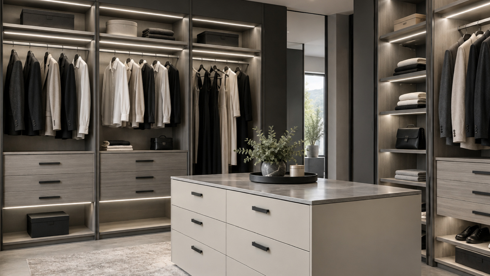
Wardrobe LED lighting should be planned as a furniture system, not as a strip and sensor added after the cabinet is built. Fix the activation method, profile position, door clearances, cable route, driver and sensor access, and expected switch-off behavior on the furniture drawings. Then review actual strip, profile, sensor and control candidates against those conditions.
Start with the user action, not the sensor label
Write the expected sequence in plain language. A useful brief might say: “The light turns on when either door opens, stays on while the wardrobe is in use, and turns off after the doors are closed.” That statement is more useful than asking for a “motion sensor” without defining the behavior.
Choose the activation method from the furniture and use case.
| Activation method | Useful starting condition | Questions to resolve |
|---|---|---|
| Door-position sensing | A hinged or sliding door has a repeatable open and closed position | Which door controls which zone? Where can the sensor and target sit without collision? |
| Presence or motion sensing | The light should respond to a person approaching or reaching into an open space | What is the detection field? Could corridor movement or an adjacent door cause false activation? |
| Touch control | The user can reach a defined control point | Is the control visible, intuitive and accessible after installation? |
| Furniture switch | A simple physical contact can be integrated into the cabinet | Can the switch tolerate the door movement and remain serviceable? |
| External control | The wardrobe belongs to a larger room-control system | What interface, zone behavior and commissioning responsibility apply? |
The labels above describe control approaches, not interchangeable products. Detection distance, field, delay, wiring logic, input voltage and load limits must come from the exact sensor or controller documentation.
Draw the profile and sensor into the wardrobe section
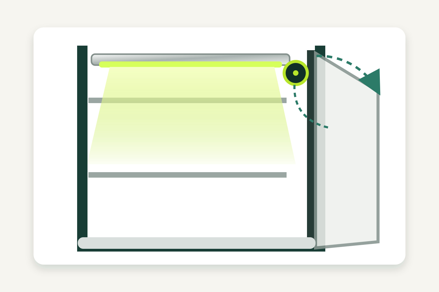
Use a section drawing for each different cabinet condition. Show shelves, hanging rails, doors, hinges, drawers, handles and decorative panels. A lighting position that works in an open wardrobe may cause glare, shadowing or hardware conflict in a deep cabinet.
Review these questions on the drawing:
- Does the profile illuminate the intended hanging, shelf or drawer zone?
- Is the light source screened from normal standing and seated sightlines?
- Does the diffuser or profile conflict with door travel, hinges or shelf pins?
- Can the strip and profile be installed without forcing a bend at a corner?
- Is there room for cable entry, connector clearance and strain relief?
- Can the sensor see or contact its intended target without obstruction?
The wardrobe and furniture lighting guide provides the current application route. Use it to organize the room and furniture context before requesting a system review.
Separate lighting zones before routing cables
One long electrical zone is not always the same as one useful furniture zone. Separate zones where doors, cabinets or user actions differ. For example, two independently opened wardrobe bays may need separate activation even when they share a driver location.
Create a simple zone schedule.
| Zone | Trigger | Light location | Cable exit | Control location | Service access |
|---|---|---|---|---|---|
| Left hanging bay | Defined after sensor review | Front vertical or top horizontal profile | Mark on cabinet drawing | Mark on drawing | Removable top panel or adjacent cabinet |
| Right shelf bay | Defined after sensor review | Shelf or vertical profile | Mark at each shelf transition | Mark on drawing | Accessible connector route |
| Drawer zone | Defined after sensor review | Above or inside drawer area | Avoid runners and moving parts | Mark on drawing | Accessible without removing fixed joinery |
Do not copy the example as a finished design. Replace every entry with the real furniture geometry and selected control method.
Route power and control paths before production
Mark the complete route from the power supply to every strip and control component. Distinguish mains-side work from low-voltage furniture wiring and assign each part to the appropriate qualified trade under local requirements.
The route should account for:
- cable entry points that will not be trapped by cabinet backs or wall fixing;
- protected transitions across panels, shelves and moving sections;
- connector and terminal space rather than cable diameter alone;
- driver ventilation, mounting orientation and access requirements;
- control-component polarity, channel and load boundaries;
- a practical way to isolate and replace failed components.
The current controls and dimming category is a discovery page, not proof that every control device works with every strip or furniture layout. Record the exact candidate model and obtain its current specification before approval.
Prevent false triggers and incomplete switch-off
False triggering is usually a coordination problem. Test the chosen sensor in a representative cabinet rather than assuming a catalogue label guarantees behavior in the final installation.
Check likely causes:
- a motion sensor can see through an opening into a circulation area;
- a door sensor target moves out of alignment as hinges or panels settle;
- reflective or dark surfaces change the behavior of an optical sensor;
- two doors share a bay but the logic accounts for only one door;
- the delay is inconveniently short or long for the user task;
- a sensor is hidden behind stored items, clothing or a trim piece;
- power cycling changes the controller state or pairing behavior.
Use the actual finish samples, door hardware and expected storage arrangement during the mockup. Record what happens when doors open individually, together and in different sequences.
Preserve service access
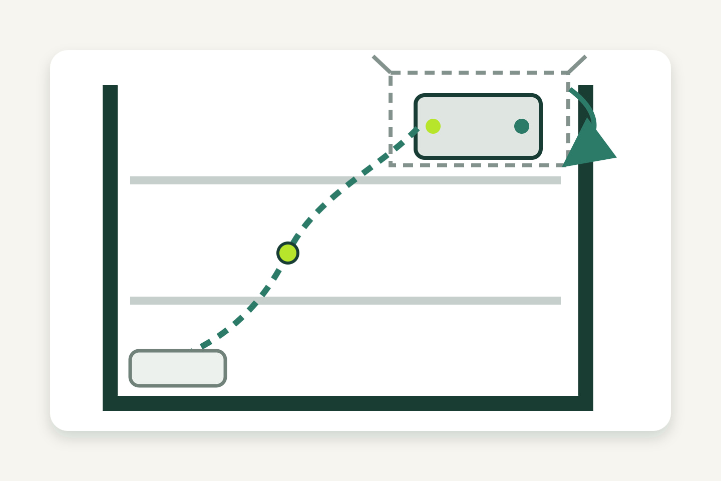
Furniture lighting can become difficult to repair when drivers and controls are sealed behind finished panels. Identify a service route on the production drawing before approving the cabinet.
The service plan should answer:
- Which panel or cover can be removed without damaging the finish?
- Can the driver, sensor and connectors be reached with ordinary tools?
- Are component labels readable after installation?
- Can one zone be isolated without dismantling the full wardrobe?
- Is spare cable length controlled and protected rather than compressed into a cavity?
- Are replacement constraints recorded with the handover information?
Use a representative furniture mockup
The mockup should reproduce the variables that affect the decision: profile recess, diffuser, door or drawer movement, finish, sensor position, cable exit and control delay. It does not need to reproduce the entire room, but it must reproduce the critical furniture section.
Review the mockup under normal ambient light and from the expected viewing positions. Operate every relevant door and drawer. Confirm that the lighting response is understandable, glare is controlled, hardware clears the lighting assembly and service parts remain reachable.
Wardrobe-lighting brief checklist
- Furniture plan, elevations and critical sections are current.
- Each lighting zone and user action is defined.
- Door, motion, touch or external-control behavior is written in plain language.
- Strip, profile, diffuser and sensor positions are shown on the drawing.
- Hinges, runners, shelves, handles and door travel have been checked for conflict.
- Cable entries and complete power/control routes are marked.
- Exact component voltage, load, channel and wiring requirements are available.
- Driver and control locations meet their installation instructions.
- False-trigger and switch-off scenarios are included in the mockup test.
- Drivers, sensors, connectors and isolation points remain serviceable.
- Acceptance notes identify the tested configuration and any open choices.
If the furniture geometry and control behavior are ready, Send Furniture Drawings for a project review. Include sections, door types, desired activation sequence, zone schedule, cable constraints and any candidate components. The review begins a compatibility check; it does not confirm a final system until the exact products and installation conditions are verified.
Sources
[1] U.S. Department of Energy, “LED Basics”. General context on integrating LED lighting with sensors and controls; exact sensor behavior remains product- and installation-specific. Accessed 2026-10-05.
Bring the comparison into a project brief.
Share the documented requirements and unresolved questions. An inquiry begins review; it does not confirm engineering approval, compatibility, stock, price, lead time, compliance or an order.
Prepare a project brief