LED Light Board OEM Brief: Mechanical, Electrical and Assembly Inputs
Build a drawing-led OEM intake for a light board or illuminated base module, with a confirmed power budget and a staged sample-approval sequence.
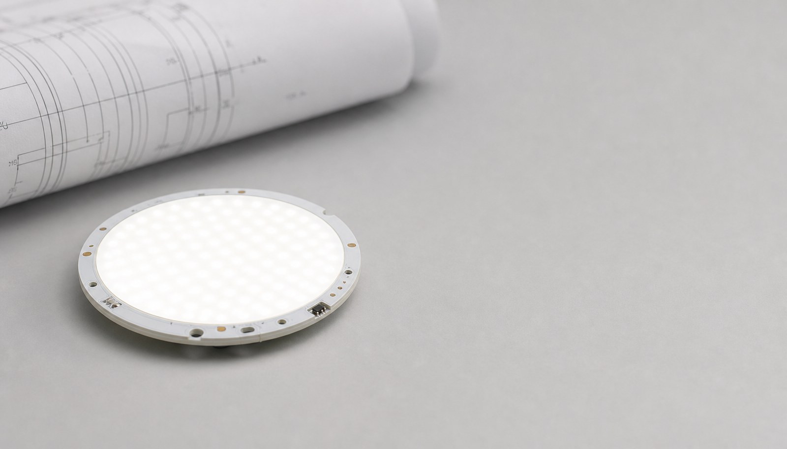
An LED light board OEM brief is a drawing-led intake, not a product description. It describes the illuminated product's intended function, supplies a drawing and available space, records electrical and connection inputs, defines optical and assembly needs, and plans a sample-approval sequence before any quotation is requested.
This guide is for product developers, brand owners and OEM procurement teams preparing a light board or illuminated base module brief. For selecting among existing light board and module products, see the LED light board module selection guide; this article covers controlled customization and assembly inputs for a modified or new design. Review the light source components category and the OEM and ODM service context before submitting a brief.
Describe the illuminated product
State what the finished product is and what role the light board plays in it, before any dimension or electrical detail.
Record:
- the product category (illuminated sign base, display stand, decorative panel, functional light module inside another assembly);
- how the board mounts and what it mounts to or inside of;
- whether the board is the visible light source or illuminates another surface indirectly;
- end-use environment (retail, exhibition, residential, outdoor).
A brief that jumps straight to electrical specifications without describing the product's role risks a technically correct board that does not fit the actual assembly or intended light effect.
Supply a drawing and available space
Provide a dimensioned drawing of the available envelope, not a verbal size estimate.
- Overall board footprint and thickness limits, including any curved or non-rectangular boundary.
- Mounting points, screw bosses, or attachment features already fixed by the surrounding assembly.
- Clearance for any driver, connector or cable routing within or adjacent to the board.
- Any existing reference part or competitor sample the board must fit alongside or replace.
A drawing is the single most load-bearing document in an OEM light-board brief. Verbal dimensions without a drawing are a frequent source of rework once a physical sample does not fit the assembly.
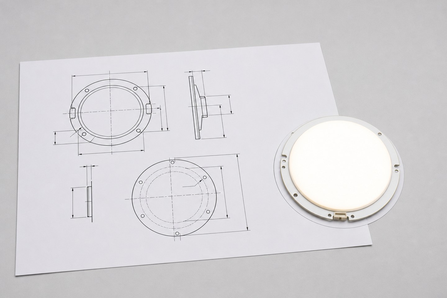
Record electrical and connection inputs
Specify the electrical interface the board must present, matched to the rest of the assembly.
| Input | What to specify | Why it matters |
|---|---|---|
| Voltage and current type | Confirmed voltage and whether constant-voltage or constant-current | Must match the driver or power source used in the final product |
| Connection method | Connector type, cable length, or direct-solder pad location | Determines how the board integrates into the assembly during manufacturing |
| Control requirement | On/off only, dimmable, or addressable with named protocol | Changes the board's internal circuit design, not just the lead wiring |
| Power budget | Maximum available current or power from the host assembly | Caps the board's achievable brightness and LED count |
Do not leave the power budget unstated. A board designed without a confirmed power ceiling risks exceeding what the host assembly's driver or battery can actually supply.
Define optical and assembly needs
State the intended visual result and the physical assembly method together, since one constrains the other.
- Light appearance needed at the viewing surface (uniform glow, defined beam, point-source accent) and the viewing distance it will be judged at.
- Diffusion or optical layer requirement, and whether it is part of the board or a separate component in the host assembly.
- Assembly method (board installed by the buyer's own line, or delivered as a pre-assembled module ready to install).
- Any requirement for the board to be serviceable or replaceable after final assembly.
Replace a general description such as "soft, even glow" with the actual viewing distance, the diffusion approach being evaluated, and the comparison method that will be used to judge the result on a sample.
Plan sample approval
Treat sample approval as a staged process, not a single yes/no decision on an early prototype.
- Initial sample: Confirms dimensional fit and basic electrical function against the drawing and power budget.
- Optical sample: Confirms light appearance and diffusion result against the stated viewing condition, under the planned assembly and ambient conditions.
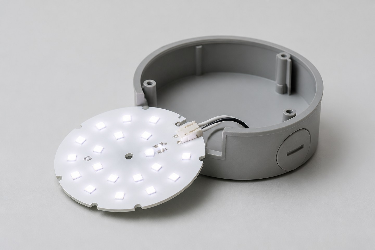
- Assembly sample: Confirms the board's connection method and mechanical fit inside the actual host assembly, not a test fixture.
- Final approval: Confirms all prior sample results remain valid in the production-intended materials and process before authorizing bulk production.
Record the result of each stage separately. Approving an early dimensional sample does not approve the optical result, and approving the optical result does not approve the in-assembly fit.
Replace vague requests with evaluable requirements
| Vague request | Why it causes rework | More evaluable wording |
|---|---|---|
| "Light board to fit our product." | No dimensioned envelope or mounting detail | Supply a dimensioned drawing of the available space and mounting points |
| "Soft, even light." | No defined viewing distance or diffusion method | Specify viewing distance, diffusion approach and comparison method for approval |
| "Standard connector." | Connection method undefined against the host assembly | Specify connector type, cable length or solder-pad location matched to the assembly |
| "Approve and move to production." | Sample stages are not separated | Record dimensional, optical and assembly-fit approval as separate staged decisions |
Account for tooling and minimum-run realities
Treat the move from a controlled sample to a bulk-manufactured product as a separate conversation from design approval, since tooling and production-batch realities change what "the same as the sample" actually means.
- Tooling dependency: Ask whether the approved board design requires dedicated tooling (a custom PCB shape, a specific mold for a housing or diffuser). If so, confirm tooling lead time and cost separately from the sample timeline, since tooling can extend the schedule well beyond sample approval.
- Process variance: Confirm what tolerance the supplier expects between the hand-built or small-batch sample and a full production run — materials, assembly process, and even ambient conditions on a production line can introduce variance that a single sample does not reveal.
- Minimum run quantity: Ask whether the approved design has a minimum production quantity tied to the tooling or material sourcing, and whether that minimum differs from a standard stock-item minimum.
Record these three answers alongside the sample-approval sequence so the full path from design to bulk production is visible before committing to tooling costs.
When the product description, dimensioned drawing, electrical inputs, optical/assembly needs and tooling expectations are documented, Submit Custom Requirement. Include the drawing, power budget, connection method, light appearance target and the sample-approval sequence proposed. The inquiry begins a feasibility and scope review for the stated design; exact dimensional tolerances, optical performance and commercial terms are confirmed in that review, not by this guide.
Bring the comparison into a project brief.
Share the documented requirements and unresolved questions. An inquiry begins review; it does not confirm engineering approval, compatibility, stock, price, lead time, compliance or an order.
Prepare a project brief