LED Light Board and Module Selection for Product Development
Build an OEM module brief from the finished product geometry, optics, electrical connection, thermal path and assembly process before sample approval.
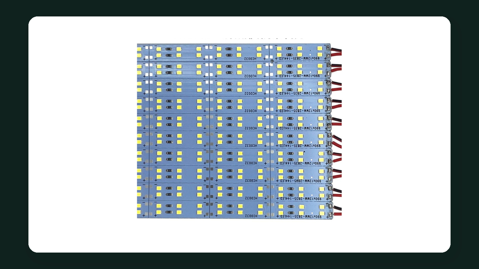
Select an LED light board or module from the illuminated part and assembly, not from diameter or voltage alone. Define the visible area, available envelope, optical stack, electrical connection, thermal path, fixing method, controls and production process. Then compare exact module candidates and approve a representative sample.
Define the illuminated part
Start with the product that must emit light: an illuminated base, display, sign element, appliance detail, furniture feature or another assembly. Provide drawings rather than a verbal size description.
The drawing should identify:
- visible illuminated area;
- outer product envelope;
- module keep-out zones;
- viewing directions and distances;
- diffuser, lens, light guide or reflective cavity;
- fixing points and assembly sequence;
- cable exits and connector space;
- accessible and sealed service areas.
State the lighting task in observable terms. Examples include an even backlit area, an illuminated edge, a decorative halo or a defined luminous symbol. Do not turn those descriptions into unverified luminance, uniformity or lifetime guarantees.
The light source components category and light boards and illuminated bases collection provide the current product-family context. Exact suitability depends on model-level data and the customer assembly.
Record the complete mechanical envelope
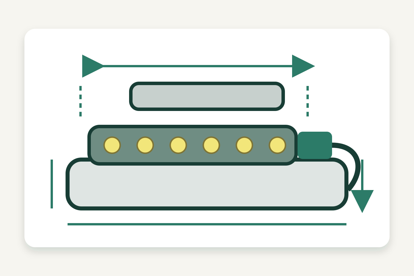
Diameter or outline is only one part of fit. A usable envelope includes the board thickness, components, connectors, wire bend, fasteners, standoffs and clearance to the optical parts.
| Mechanical input | What to record |
|---|---|
| Board outline | Diameter, length, width, shape and permitted tolerances |
| Component height | Highest component on each side of the board |
| Fixing | Hole locations, edge distances, clips, adhesive or other approved method |
| Optical spacing | Distance to diffuser, light guide, lens or reflective surface |
| Cable space | Connector body, mating action, wire bend and strain relief |
| Assembly access | Tool path, insertion direction and production sequence |
| Service access | Whether the module or complete product is replaceable |
Provide CAD or dimensioned drawings when fit is critical. A photo beside a ruler is useful context but should not replace controlled dimensions.
Match voltage, current and connection architecture
Do not request “a 12 V board” as the complete electrical specification. Record how the module is powered and controlled.
Include:
- rated input or drive method from the candidate documentation;
- nominal and permitted electrical range where specified;
- power or current basis;
- connector family, keying, pin assignment and polarity;
- cable length, conductor identification and strain relief;
- dimming or control method;
- protection and isolation requirements;
- driver or power-supply location and service access.
If the module uses a constant-current driver, do not treat it as a constant-voltage load. If it includes onboard control electronics, record the required interface and startup behavior. The exact circuit documentation decides the connection.
Create a connection schedule.
| Function | Board connection | Cable/connector | External equipment | Verification |
|---|---|---|---|---|
| Input power or drive | Record pin/pad | Record exact mating part | Record driver/supply | Drawing and sample |
| Control, if used | Record interface | Record conductor order | Record controller | Functional test |
| Other required signal | Record only when applicable | Record exact part | Record destination | Approved requirement |
Build the optical stack around the task

The board and the optical parts work together. LED position, viewing angle, board-to-diffuser distance, diffuser transmission, cavity finish and light-guide geometry can all change the visible result. The U.S. Department of Energy notes that LED device performance and fixture design both affect the useful lighting result.1
For sample comparison, control these variables:
- diffuser or lens material and thickness;
- distance from LEDs to the optical surface;
- reflective or absorbing cavity surfaces;
- aperture and border dimensions;
- drive condition and dimming level;
- viewing direction and ambient light;
- camera settings if photographs are kept as secondary evidence.
Evaluate the real product task. A board that looks even in open air may show bright points in a shallow enclosure. A board with lower measured output may produce a better finished surface when paired with the intended optics. Do not approve the module from board-only photographs.
Plan the thermal path and enclosure
LED heat must move through the circuit board and surrounding assembly. Drive current, ambient temperature and thermal path all affect operating conditions.2
Map the intended path:
LED package → circuit board → interface material or fixing → chassis or heat-spreading part → surrounding environment
Then ask:
- What board construction does the candidate use?
- Which surface is intended to transfer heat?
- Does the product chassis participate in the thermal path?
- Is the module enclosed near other heat sources?
- Will adhesive, air gaps, paint or plastic interrupt heat transfer?
- What limits and mounting instructions does the module supplier specify?
- Can temperature be checked at a defined accessible point in the sample?
Do not assign a universal heat sink or temperature limit. Use the exact module’s documentation and review the complete assembly under its intended operating condition.
Coordinate production assembly
The module should fit the real manufacturing sequence. A technically suitable board can still fail production review if connectors cannot be reached or cables are trapped during closure.
Document:
- incoming inspection identification;
- electrostatic-discharge handling where required by the component instructions;
- fixture or locator used to position the board;
- fastening or bonding process;
- connector mating and cable routing;
- visual and functional checks before enclosure closure;
- rework and rejection boundaries;
- traceability between module revision and finished product.
Keep production claims proportional to evidence. A laboratory sample does not prove cycle time, yield or production capacity.
Define the approval sample
The approval unit should use the intended module, driver, control, optics, enclosure, mounting and cable arrangement. Record deviations if production parts are not yet available.
Review at least:
| Review area | Acceptance evidence |
|---|---|
| Mechanical fit | Dimensioned fit check and assembly photos |
| Connection | Approved pinout, mating parts and polarity record |
| Optical result | Observation in the intended optical stack and viewing condition |
| Control | Required switching, dimming or scene behavior |
| Thermal integration | Test condition, operating duration and recorded measurement method if specified |
| Assembly | Repeatable work steps and access to tools/connectors |
| Service | Replacement or non-serviceable boundary stated clearly |
A sample approval applies to the recorded configuration. Changes to LEDs, board layout, component height, connector, driver, optics, material or enclosure can require renewed review.
Module-requirement checklist
- Illuminated-part drawing and optical task are defined.
- Complete board and component envelope is available.
- Fixing points, tolerances and assembly direction are shown.
- Optical stack materials and distances are recorded.
- Electrical architecture, pinout, polarity and mating connector are documented.
- Driver, controller and cable arrangement are defined.
- Thermal path and operating environment are reviewed.
- Production assembly, inspection and traceability needs are stated.
- Service or non-serviceable boundary is explicit.
- Approval sample includes the intended surrounding assembly.
- Any change requiring renewed review is listed.
To compare or develop a module for a defined product, Submit a Module Requirement. Include drawings, target function, optical stack, available space, connection and control needs, assembly method, quantity, destination and sample-approval plan. Missing model-specific values should remain open inputs until documentation and samples are reviewed.
Sources
[1] U.S. Department of Energy, “LED Basics”. General context on how LED devices and fixture design together affect useful lighting performance; not evidence for a specific module. Accessed 2026-10-05.
[2] U.S. Department of Energy, “Thermal Management of White LEDs”. General thermal-path principles; exact product limits and assembly instructions control. Accessed 2026-10-05.
Bring the comparison into a project brief.
Share the documented requirements and unresolved questions. An inquiry begins review; it does not confirm engineering approval, compatibility, stock, price, lead time, compliance or an order.
Prepare a project brief