Waterproof COB LED Strip Selection: Construction, Connections and Use Boundaries
Define the real exposure, then match one COB strip construction with the required cut, sealed connection, drainage, mounting and service plan instead of treating one IP label as a complete outdoor-system guarantee.
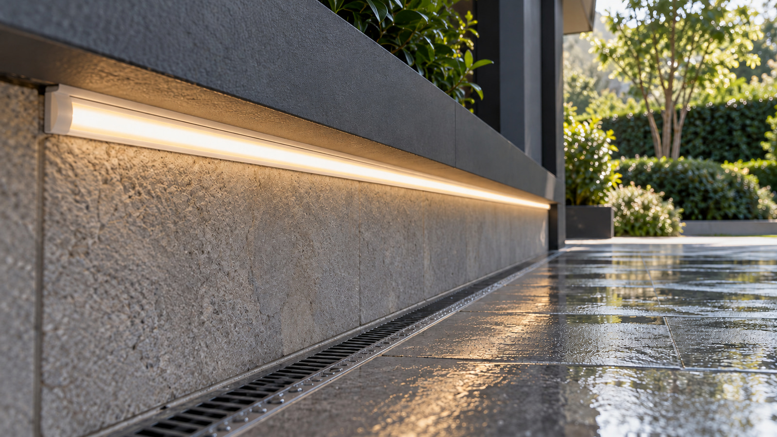
Choose a waterproof COB LED strip from the installation conditions outward: record water direction, exposure duration, drainage, joint locations and service access; then verify the exact strip construction, cut interval, connection treatment and power-equipment protection for one SKU. An IP rating for the strip does not automatically cover cut ends, connectors, drivers or the finished installation.
This is the practical starting point for waterproof COB LED strip selection. If you first need to understand what an enclosure rating does and does not describe, read our IP-rating limits for LED strip systems. The IEC describes IEC 60529 as a classification of protection provided by enclosures; it is not a blanket approval for every component or every installed condition (IEC 60529 overview).
Define the actual exposure before choosing the strip
“Outdoor” is not one environment. A strip under a ventilated canopy, a strip exposed to direct rain and a strip installed where water can collect create different requirements even when they share the same project label. Describe the route before comparing products.
| Project input | What it changes | Information to send |
|---|---|---|
| Location | Determines whether the route is dry, damp or directly exposed | Indoor, sheltered outdoor or exposed outdoor location |
| Water source | Changes the protection and connection review | Rain direction, wash-down or cleaning water, condensation and splash direction |
| Exposure pattern | Separates brief wetting from persistent exposure | Expected frequency and duration; whether water may remain after exposure |
| Installation orientation | Affects where water can travel or collect | Horizontal, vertical, face-up, face-down or edge-mounted route |
| Drainage | Identifies low points and trapped sections | Drainage direction, low points, channels, recesses and blocked exits |
| Temperature and chemicals | May affect material suitability | Ambient range and any cleaners, oils, salt or other chemicals specified by the project |
| Connections | Often create a different protection boundary from the strip body | Number and location of cuts, joints, feeds and cable exits |
| Power and control equipment | Requires its own environmental plan | Driver, controller and isolation-equipment location and enclosure |
| Service access | Determines whether a failed section can be replaced | Access panels, removable profiles, safe isolation and replacement route |
Do not reduce an outdoor COB strip request to “IP67 required.” If immersion, pressure washing, chemicals, a marine environment or a pool zone is involved, request model-specific documentation for that condition. A general product label is not enough to establish suitability.
Match the protection construction to the environment
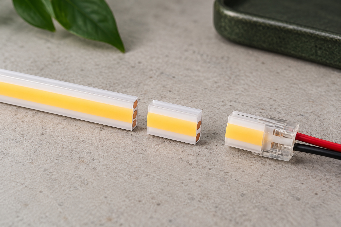
First identify the physical construction, then identify the exact SKU. A coating, encapsulation or sleeve changes the finished cross-section, bending behavior, cut treatment and available accessories. Two products described as waterproof may therefore require different mounting and connection plans.
Use this sequence:
- Define the exposure and route.
- Select the required construction type and finished dimensions.
- Confirm the exact SKU, protection rating and permitted use boundary from its documentation.
- Confirm cut interval, bend direction, lead exit, end treatment and matching accessories.
- Review a representative sample in the intended mounting space.
For example, ULT-1E5B33A3 is a specific 220V silicone-encapsulated COB strip-set family. Its listed construction includes 288 LEDs/m, a 50 cm cut interval and IP67 protection. ULT-1E5B33A3-V0001 and V0003 are both listed as 6000K, 1 m configurations with an inline switch, but one uses a two-flat-pin plug and the other an EU round-pin plug. Those fields describe those exact set configurations; they do not make the plug, switch or protection treatment universal across all COB products or every installation.
Use the current COB LED strip range and waterproof LED strip range to identify candidates, then compare the model-level fields below.
| Field | Why it matters |
|---|---|
| Coating, encapsulation, sleeve or uncoated board | Establishes the strip-body construction being evaluated |
| Exact IP rating, where documented | Describes the rated enclosure boundary, not every attached part |
| Finished width and height | Determines channel, recess and clip fit |
| Permitted bend direction and minimum radius | Prevents a route from demanding an unsupported bend |
| Cut interval | Determines achievable section lengths |
| Lead and cable exit direction | Affects routing and water entry risk |
| End caps and matching accessories | Defines what is available for the selected construction |
| Installation-space limits | Confirms that the protected strip still fits the planned route |
Plan cuts, ends and sealed connections as separate decisions
Every cut can change the protection boundary. Decide whether the supplier should provide factory-prepared lengths or whether the installer will cut and terminate on site. The quotation should identify each planned cut, feed and joint rather than treating connection work as an undefined installation detail.
For each connection, record:
- the strip SKU and marked cut position;
- the finished section length;
- whether the connection is factory-prepared or site-made;
- the lead direction and cable route;
- the connector, cap or other model-specific accessory requested;
- who is responsible for the end treatment;
- where the joint will sit relative to water and drainage; and
- how the completed section will be inspected before use.
Do not assume that a field-cut end retains the strip body's rating. Equally, do not specify a generic adhesive, curing time, torque or wiring sequence without the selected product's instructions. The useful RFQ question is: “What model-specific end and connection treatment applies to these exact lengths and locations?”
Design mounting and drainage around the installed route
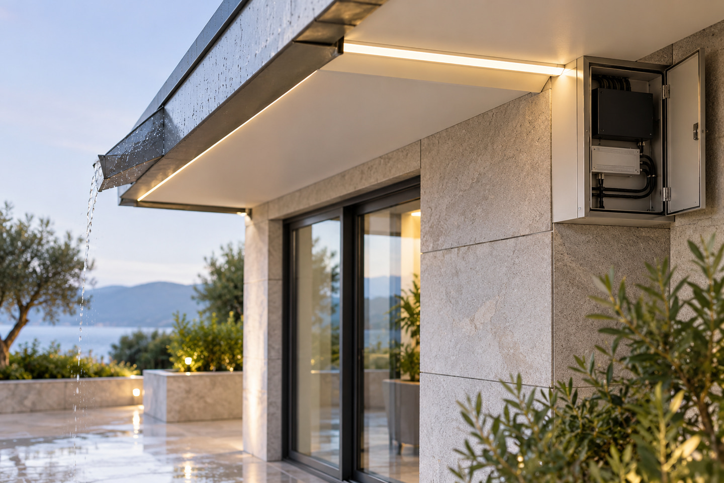
Protection works with route design, not instead of it. A channel that holds water around a joint can create a poor installation even when the strip body has a documented rating. Draw the complete route and mark changes in direction, low points, feeds and removable sections.
Use this mounting review:
- Show which way the luminous face and any opening or cable exit will point.
- Identify low points and provide a route for water to leave rather than collect.
- Avoid recesses that create a continuous water trap around the strip or connections.
- Mark corners and bends so the selected strip is not twisted into an unsupported direction.
- Define the profile, clips or other fixing method for the exact strip dimensions.
- Keep joints above predictable collection points where the layout permits.
- Locate drivers and controllers in an environment suitable for those devices.
- Preserve ventilation and heat-transfer conditions required by the selected products.
- Provide access to feeds, connections and replaceable sections.
This checklist is not a construction drawing. Fixing spacing, bend radius, maximum run length and feed arrangement must come from the exact product and system design rather than from a generic waterproof-strip rule.
Set maintenance and use boundaries before the quotation
A maintainable route lets a technician isolate, identify and replace a section without dismantling the entire installation. Define that outcome while the route is still being planned.
| Maintenance question | Decision to record |
|---|---|
| Who can access the route? | Authorized role and safe access method |
| Can the strip or profile be removed? | Removable cover, clip or access-panel requirement |
| How will a failed section be identified? | Zone labels, section lengths and feed-point records |
| What must be kept as a matched spare? | Exact strip SKU, prepared section or model-specific end accessories |
| How will the area be cleaned? | Cleaning method and chemicals to be reviewed against documentation |
| What records are required? | SKU, route drawing, cut schedule, connection method and applicable instructions |
| What should the sample prove? | Fit, bend route, connection access, drainage relationship and appearance |
Stop and request model-level documentation when the environment exceeds the stated use boundary, when cut or connection treatment is unclear, or when the route prevents drainage or service. Do not replace a missing answer with a broad “waterproof” assumption.
Send one environment and run brief for review
Copy and complete this brief for each distinct route:
| RFQ field | Buyer input |
|---|---|
| Candidate product and SKU | |
| Application and exact location | |
| Indoor, sheltered or exposed condition | |
| Water direction, frequency and duration | |
| Temperature or chemical exposure | |
| Total length and branch lengths | |
| Number and position of feed points | |
| Planned cut lengths and joint count | |
| Mounting direction, recess or profile | |
| Drainage path and low points | |
| Factory-prepared or site-made connections | |
| Driver and controller location | |
| Service-access method | |
| Sample or short-section review needed | |
| Quantity and destination | |
| Required model documents |
Send the environment, route, candidate SKU, section lengths, cut and connection plan, power-equipment location, quantity, destination and required documents through Submit Environment and Run Details.
Bring the comparison into a project brief.
Share the documented requirements and unresolved questions. An inquiry begins review; it does not confirm engineering approval, compatibility, stock, price, lead time, compliance or an order.
Prepare a project brief