Rigid LED Bar or Flexible LED Strip? A Format-Selection Checklist
Choose the format that fits the real path, mounting surface, optical assembly, connections and service plan instead of ranking formats in isolation.
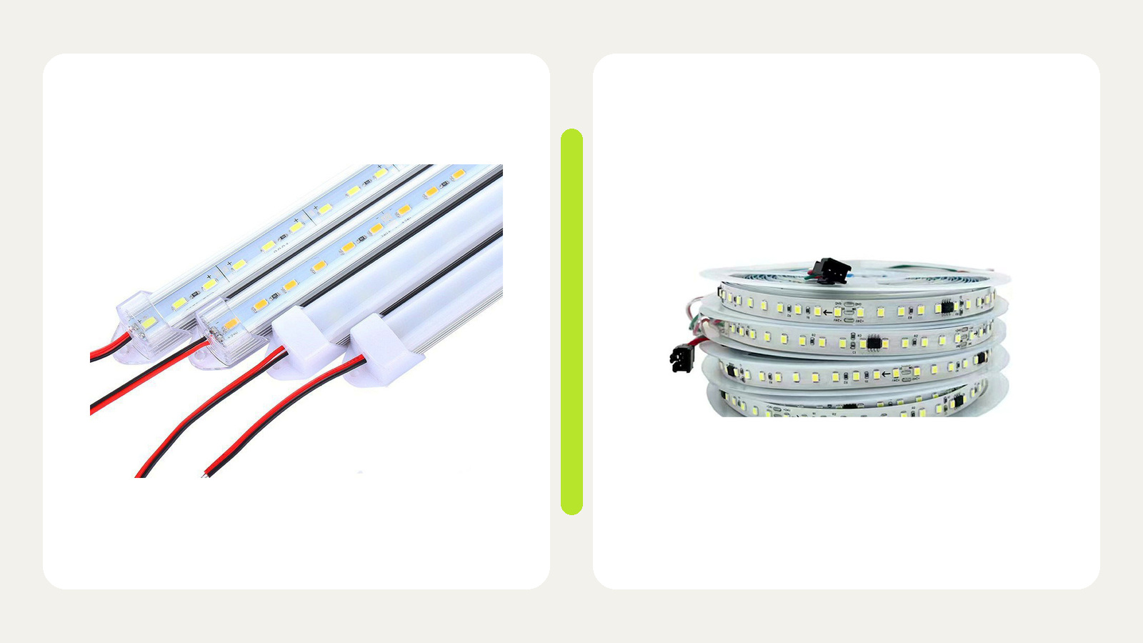
A rigid LED bar is usually the stronger starting format when the project needs a straight, repeatable module with defined fixing and connection points. A flexible LED strip is usually the stronger starting format when the light path must follow site dimensions, curves or cut-to-length layouts. Neither format is automatically better: compare geometry, mounting, thermal path, joins, wiring and replacement access with real samples.
Make geometry the first decision

Draw the illuminated path and the space available for the light source. Mark straight runs, corners, curves, gaps, obstacles and visible ends.
| Geometry question | Rigid bar implication | Flexible strip implication |
|---|---|---|
| Must the source remain mechanically straight? | A rigid substrate or housing can provide a defined straight module | Strip straightness depends on mounting surface, profile and installation quality |
| Are there curves or changing planes? | May require separate bars, angled joints or gaps | May follow permitted curves, but only within the strip’s bending and cutting rules |
| Are repeated modules preferred? | Standardized lengths and connection points may simplify repetition | Site-cut lengths may better fit varying dimensions |
| Is the source directly visible? | Board, housing, optics and connections must meet the appearance requirement | A suitable profile and diffuser may be needed to control the visible line |
| Is space extremely constrained? | Exact bar section and connector clearance govern fit | Strip width, profile depth, bend space and cable exit govern fit |
Do not use “flexible” to mean the strip can bend in any direction or fold at any point. Likewise, “rigid” does not guarantee a perfectly continuous light line between modules. Check the exact mechanical drawing and sample.
The current rigid and linear lighting category and flexible LED strip category are the two relevant discovery routes. Compare actual candidate records rather than category names.
Compare the mounting method
A rigid bar may use clips, screws, brackets, adhesive or an integrated housing. A flexible strip may use its backing adhesive, a separate profile, clips or another approved method. The substrate and installation environment decide whether that method is suitable.
Review:
- surface material, flatness and cleanliness;
- fixing points and whether drilling is permitted;
- expansion, vibration or repeated furniture movement;
- profile or housing dimensions;
- cable and connector clearance at each end;
- visibility of clips, screws, joints and wires;
- removal method without damaging the finished surface.
Avoid assuming adhesive alone will correct a rough, curved or contaminated surface. Use the exact product instructions and a representative material sample.
Treat the thermal path as a system condition
LED performance depends on moving heat away from the LED through the circuit board and surrounding structure. The U.S. Department of Energy identifies drive current, thermal path and ambient temperature as key factors affecting LED junction temperature.1
That principle does not mean every rigid bar has better thermal performance than every flexible strip. Compare the actual construction and mounting condition:
- Does the rigid bar use a metal-core board, metal housing or another defined heat path?
- Is a flexible strip bonded continuously to a suitable profile or surface?
- Are air gaps, thick adhesive layers or insulating materials interrupting the path?
- Is the assembly enclosed in a small cavity with limited air movement?
- What ambient and surface-temperature limits apply to the exact product?
- Do the installation instructions require a particular mounting orientation or profile?
Do not publish an operating-temperature or lifetime claim from format alone. Obtain model documentation and test the assembly where the thermal condition is important.
Plan wiring, joins and corners
Rigid bars often create repeated module-to-module or cable-to-module connection points. Flexible strips reduce some module joints but may require field cuts, corner cables or feeds along long layouts.
Create a connection schedule for both options.
| Location | Rigid-bar option | Flexible-strip option | Decision evidence |
|---|---|---|---|
| Straight run | Number and length of modules | Cut length and profile | Drawing and sample fit |
| Corner | Angled module, cable link or gap | Permitted bend, cable corner or separate section | Mechanical rules and visual sample |
| Power entry | End or rear feed arrangement | End, mid or multiple feed plan | Load and voltage-drop review |
| Service joint | Plug, terminal or replaceable module | Connector, soldered lead or replaceable section | Approved service method |
The fewest connections are not always the best answer. A long concealed assembly may be easier to service when divided into accessible modules, while many visible rigid-bar joints can interrupt appearance. Compare the real project priorities.
Compare light appearance with the full optical assembly
The LED format alone does not determine the finished light line. Diffuser distance, profile geometry, LED pitch, surface reflectance and viewing angle all influence what the user sees.
For a fair comparison:
- use candidates with the required light output and color specification;
- install them in the intended profile, housing or recess;
- use the intended diffuser or lens;
- observe from normal viewing positions;
- compare straightness, visible points, joint shadows and end conditions;
- test dimming behavior with the intended control system.
Do not use photography alone to approve the light line. Camera exposure and image processing can hide or exaggerate brightness differences and visible points.
Plan replacement before choosing the format

Define the likely service unit. It may be one rigid bar, one driver, one connector, one flexible-strip section or a complete profile assembly.
Ask:
- Can a failed unit be removed without dismantling finished joinery or displays?
- Are connectors and fasteners reachable?
- Can a replacement be identified from the handover record?
- Will a replacement section create a visible color or brightness mismatch?
- Is there a safe isolation point?
- Does the wiring allow one section to be tested independently?
A replaceable rigid module may simplify service in one project. A continuous flexible strip with an accessible profile may be simpler in another. The drawing should show the service route for the chosen solution.
Build a controlled comparison sample
Use the same installation section, power and control conditions for both formats wherever possible. Label every candidate and record what changed.
Score the decision against project requirements, not a universal ranking.
| Criterion | Required condition | Rigid-bar observation | Flexible-strip observation |
|---|---|---|---|
| Geometry | State path and tolerances | Record sample result | Record sample result |
| Appearance | State viewing and diffuser condition | Record result | Record result |
| Mounting | State substrate and access | Record method | Record method |
| Connections | State allowed joint locations | Record count and visibility | Record count and visibility |
| Thermal integration | State mounting and ambient condition | Record evidence | Record evidence |
| Service | State replacement route | Record steps | Record steps |
Format-selection checklist
- The actual light path and available section are drawn.
- Straight runs, curves, corners and gaps are identified.
- Exact candidate dimensions and cut or module lengths are available.
- Mounting surface and fixing method are defined.
- Thermal path and enclosure conditions are reviewed for each candidate.
- Wiring, feeds, joins and corner methods are scheduled.
- Finished appearance is compared in the intended optical assembly.
- Driver and control compatibility are checked separately.
- Service unit, access route and replacement record are defined.
- A representative comparison sample records the actual configurations.
To Compare Candidate Formats for a project, send the layout drawing, available section, mounting surface, required light appearance, operating environment, control needs, quantity and destination. The sample should decide the project condition; the format label should not decide it in advance.
Sources
[1] U.S. Department of Energy, “Thermal Management of White LEDs”. General explanation of the LED thermal path and the roles of drive current, ambient temperature and thermal design; exact product limits and instructions control. Accessed 2026-10-05.
Bring the comparison into a project brief.
Share the documented requirements and unresolved questions. An inquiry begins review; it does not confirm engineering approval, compatibility, stock, price, lead time, compliance or an order.
Prepare a project brief