LED Strip Connector Matching: Width, Pin Count, Polarity and Coating
Use the exact strip sample to match connector dimensions, contacts, conductor order and coating treatment before approving a bulk configuration.
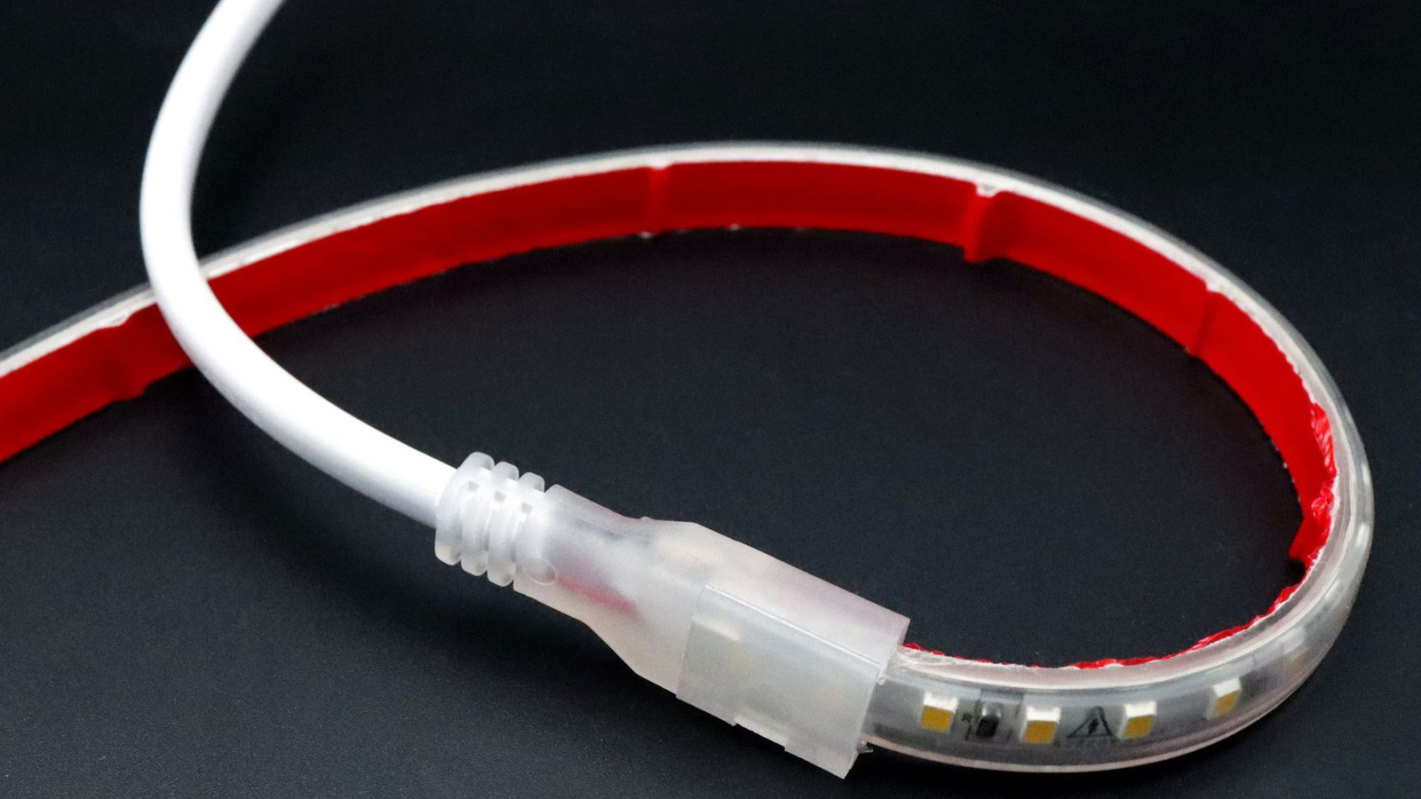
An LED strip connector should be selected only after the exact strip has been identified. Match the strip width, copper-pad geometry, channel count, polarity or conductor order, coating condition and installation environment. A connector that appears to fit can still make the wrong electrical contact, damage a coating or fail to close around the strip.
Identify the strip before searching for a connector
Use the actual strip sample and its current drawing or datasheet. Do not select from a generic product-family name such as “COB connector” or “RGB connector.” Different strips in the same family can use different widths, pad positions, conductor orders and protective constructions.
Record these fields first:
| Strip field | What to inspect | Why it matters |
|---|---|---|
| Exact identification | Model, revision, batch reference or approved sample | Prevents matching against a similar but different strip |
| Overall width | Finished strip width, including relevant coating or jacket | Determines whether the strip enters and clamps correctly |
| Pad layout | Pad count, pad width, spacing, position and cut mark | Determines whether contacts land on conductive areas |
| Electrical order | Polarity or channel sequence as marked and documented | Prevents reversed or crossed connections |
| Strip construction | Bare board, surface coating, encapsulation or jacket | Changes access to pads and the connector body required |
| Intended cut | Permitted cut line and prepared end condition | Prevents loss of contact area or damage outside a cut point |
| Environment | Indoor, damp, dusty, washable or other defined condition | Sets sealing, enclosure and maintenance requirements |
The current connector collection can help identify candidate connector types. Treat each listing as a starting point and verify the exact configuration before ordering.
Match width and pad geometry separately
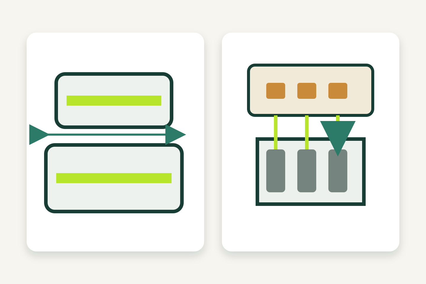
“Same width” is necessary but not sufficient. A connector may accept the strip body while its contacts miss the pads. Conversely, the contact pattern may look similar while the housing is too narrow for a coated strip.
Use a close-up inspection sequence:
- measure the finished strip width at more than one point;
- compare the connector’s stated strip-width range with the actual sample;
- align every connector contact with the center of its intended copper pad;
- check that no contact bridges adjacent pads;
- confirm the cut end seats to the intended depth without forcing;
- close the latch and check that the strip remains flat and retained;
- inspect the connection from both sides where the housing permits.
Do not remove coating, scrape pads or trim the circuit board unless the connector and strip instructions explicitly require that preparation. Field alteration can change mechanical retention, electrical contact and environmental protection.
Match channel count and conductor order
Pin count is a physical count. It does not prove the electrical order is correct. Two multi-channel strips can have the same number of pads but assign common supply and color channels differently.
Create a one-to-one mapping before connection.
| Strip marking or documented function | Connector contact | Cable conductor | Downstream terminal |
|---|---|---|---|
| Record exact strip mark | Record position | Record color and label | Record controller or supply terminal |
| Record next channel | Record position | Record color and label | Record terminal |
| Continue for every pad | Continue for every contact | Continue for every conductor | Continue for every terminal |
Use the strip and controller documentation as the authority. Cable colors are identification aids, not proof of function. If a premade connector cable changes conductor order between ends, record that change explicitly.
Check polarity before applying power
For a single-color constant-voltage strip, verify the positive and negative path from the strip pads through the connector and cable to the power source or control device. For multi-channel systems, verify the common conductor and every controlled channel.
Before applying normal operating power:
- compare the strip markings with the approved wiring schedule;
- inspect contact alignment and any exposed conductive material;
- confirm the power source and controller are isolated;
- use the project’s approved continuity and polarity check method;
- correct any ambiguity before energizing the assembly.
Testing procedures, instruments and energization must follow the project’s electrical-safety requirements and the instructions for the exact components. This guide does not replace qualified electrical review.
Treat coating and jackets as part of the match
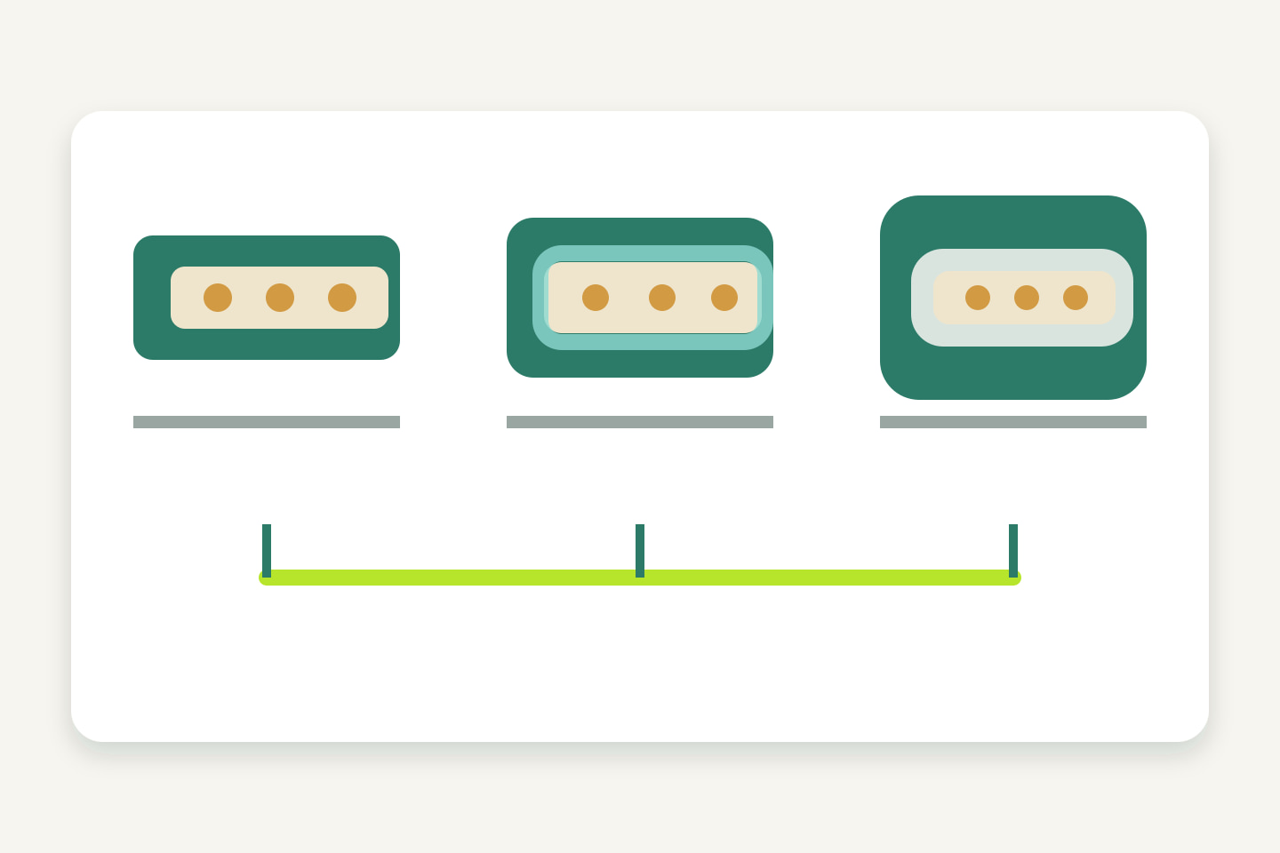
A connector designed for an uncoated strip may not close correctly around a coated or encapsulated strip. A connector intended to pierce or displace a specific coating should not be assumed to work with a different material or thickness.
Ask these questions:
- Is the connector explicitly intended for the strip’s protection construction?
- Must the end be prepared, and if so, what preparation is permitted?
- Does the housing seal around the strip, or is a separate enclosure or seal required?
- Can the latch close without crushing the board or distorting the jacket?
- Does the preparation method expose conductive material beyond the connector body?
- Can the completed joint be inspected and serviced?
An IP rating on one component does not establish the protection of the completed field joint. The IP Code classifies protection provided by enclosures; the assembled connection still needs evidence for its exact scope and configuration.1
Include the environment and mechanical load
The connector should not carry cable tension or repeated movement unless its instructions explicitly allow it. Plan strain relief and support so the strip pads and contact interface are not used as a mechanical anchor.
Review:
- pull direction and cable support;
- minimum space to close and reopen the connector;
- bends immediately beside the housing;
- vibration or movement from doors, displays or furniture;
- condensation, cleaning and dust exposure;
- temperature limits for the connector, strip and enclosure;
- access for inspection and replacement.
For broader category discovery, review the connectors and accessories category. The category route does not establish compatibility between any two listed items.
Validate a sample before bulk ordering
Build the sample with the intended strip, connector, cable, controller or power supply, and any required enclosure or sealing materials. Use the same preparation tools and work instructions planned for production.
Record the result rather than relying on “lights on” as the only test.
| Sample check | Evidence to keep |
|---|---|
| Physical fit | Photos of strip insertion, latch closure and contact position |
| Electrical mapping | Approved pad-to-contact-to-conductor schedule |
| Retention | Defined handling check and observed result |
| Environment | Required enclosure/sealing method and its scope |
| Assembly | Preparation steps, tools and rejected conditions |
| Service | Reopening or replacement method if the joint is serviceable |
One passing sample does not authorize substitutions. If the strip revision, width, pad pattern, connector, cable or coating changes, repeat the affected checks.
Connector-matching checklist
- Exact strip model or approved sample is identified.
- Finished strip width is measured and recorded.
- Contact positions align with every copper pad.
- Pin count and electrical channel order both match.
- Polarity is traced through the complete connection.
- Coating or jacket preparation follows documented instructions.
- Connector closure does not crush, bow or displace the strip.
- Cable tension and movement are controlled outside the contact interface.
- Environmental protection is verified for the completed joint, not inferred from one part.
- A representative sample has been assembled and documented.
- Bulk-order records name the exact strip and connector configuration.
To compare a real strip and connector combination, Request Connector Matching with samples. Send the strip identification, clear pad close-ups, finished width, channel order, coating condition, intended environment, quantity and destination. No compatibility conclusion should be made from product names alone.
Sources
[1] International Electrotechnical Commission, “IEC 60529: Degrees of protection provided by enclosures (IP Code)”, edition 2.0 with amendments. Used only for the scope of enclosure-protection classification; it is not evidence that a completed connector joint has a particular rating. Accessed 2026-10-05.
Bring the comparison into a project brief.
Share the documented requirements and unresolved questions. An inquiry begins review; it does not confirm engineering approval, compatibility, stock, price, lead time, compliance or an order.
Prepare a project brief