Cove Lighting Layout: Inputs to Fix Before Selecting an LED Strip
Fix the cove section, viewing lines, receiving surface, electrical branches, control zones and service route before selecting a strip.
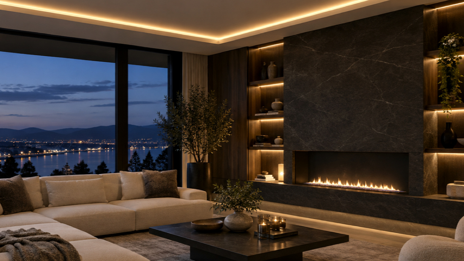
A cove-lighting layout should be fixed in section before an LED strip is selected. The section defines whether the source is visible, where light lands, how surfaces reflect it, how long the electrical runs are, where feeds and control zones belong, and whether the strip, profile, driver and connections can be serviced. There is no universal setback or profile position: compare candidate geometry in the actual cove and viewing conditions.
Draw the cove section before choosing a strip
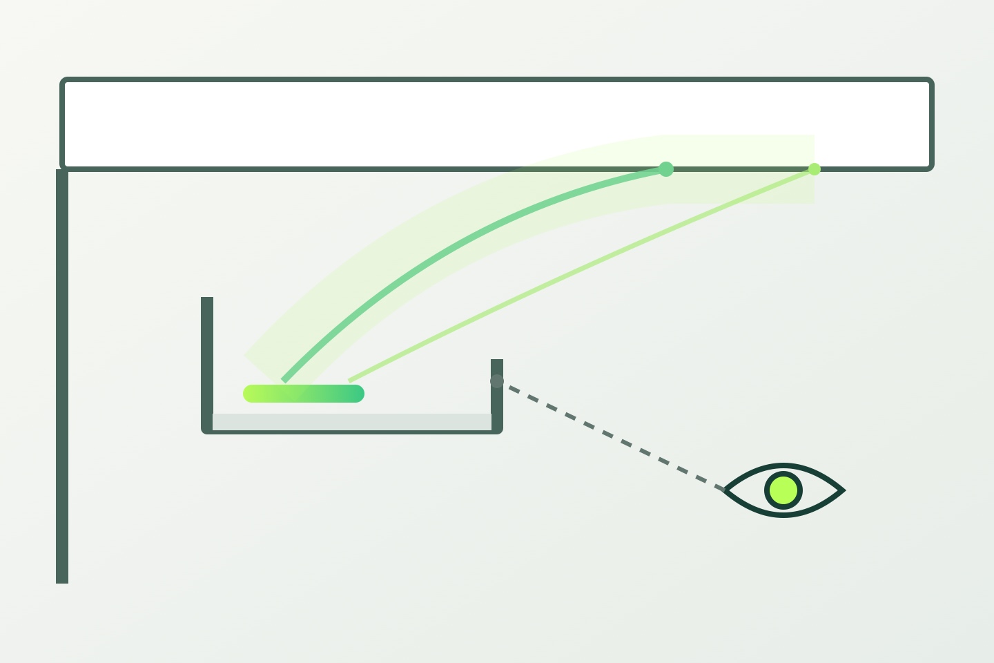
Prepare a dimensioned section through every distinct cove type. Show ceiling and wall planes, cove lip, recess, intended strip or profile position, likely viewing lines and access route. A plan alone cannot show whether occupants will see the source or whether the cove blocks useful light.
Record:
- cove width, depth and lip geometry;
- strip position and aiming direction;
- distance to the illuminated wall or ceiling surface;
- primary viewer locations and eye lines;
- surface material, color and finish;
- obstructions, joints and level changes;
- access panels or removable elements.
Use the living room and cove application page for context, then replace generic concepts with the project's actual section.
Control direct view and reflected glare
The first visual question is not brightness; it is what the viewer can see. Check sightlines from entrances, stairs, seating, beds, upper floors and reflective surfaces. A strip concealed from one position may be visible from another.
Also inspect reflected images in glass, polished stone, metal, glossy paint and dark screens. The cove lip may hide the source directly while a nearby surface reveals it.
Do not use one universal setback. Compare locations by reviewing:
- source concealment from the agreed positions;
- distribution across the target surface;
- bright bands, scallops or dark edges;
- reflections and glare;
- tolerance to construction variation;
- space for the selected profile, connectors and cable exits.
A physical mockup or representative section can answer these questions more reliably than a rendering that does not reproduce material reflectance or actual output.
Coordinate surface finish and light distribution
Indirect lighting depends on the surface that receives and redistributes the light. Color, gloss, texture, flatness and joint quality can alter the visible result. Record the final finish rather than evaluating only a primer or unfinished mockup.
LED products also vary in light distribution, color and efficacy, and overall performance depends on fixture and optical integration.1 Compare exact strip/profile candidates under the representative cove geometry. Avoid claiming a specific illuminance or perfectly uniform line without a reviewed photometric method and verified product data.
| Geometry input | What to review | Evidence |
|---|---|---|
| Strip position | Concealment and distribution | Dimensioned section and sample |
| Aiming direction | Target surface and spill | Section/elevation review |
| Cove lip | Sightline control and shadow edge | Viewer-position checks |
| Surface finish | Reflection, color and visible defects | Approved finish sample |
| Profile/diffuser | Fit, light spread and service | Exact component data and mockup |
| Construction tolerance | Sensitivity to misalignment | Detail and site-quality plan |
Plan runs, feeds and power by branch
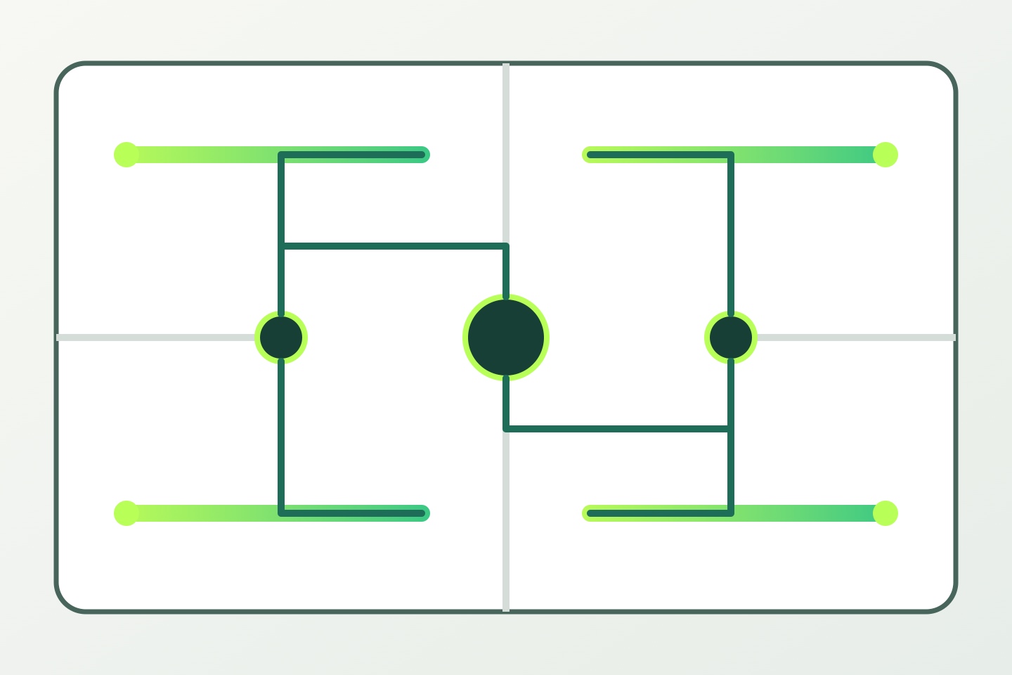
Translate the architectural line into electrical branches. Mark the length of each branch, driver-to-feed distance, joints, corners, level changes and accessible feed points. Do not treat the total perimeter as one continuous run without checking the selected strip and system instructions.
Calculate each branch load from verified power per unit length. Use the exact driver's loading and derating rules. Voltage drop depends on current, conductor resistance, path and connections, so conductor and feed planning needs a reviewed calculation rather than a universal injection interval.2
Consider whether the layout can be divided at architectural breaks, access points or control-zone boundaries. Every additional feed must be included in the drawing and protection plan.
Review published flexible LED strip categories only to organize candidate discovery. The category does not confirm voltage, continuous length, power, compatibility or availability for the project.
Choose control zones around use and operation
Control zones should follow how the space is used, not only how the ceiling is wired. Record which coves operate together, which require separate dimming or scenes, and how users control them. Hospitality, residential and commercial projects can have different schedules and commissioning needs.
Define:
- normal operating scenes;
- independent zones and their boundaries;
- dimming or control interface;
- switching and schedule behavior;
- default state after power restoration;
- commissioning responsibility and retained settings;
- access to controllers, amplifiers and drivers.
Check visible transitions where adjacent zones meet. Two separately controlled branches may create an obvious discontinuity if their ends or scenes are not coordinated.
Preserve installation and service access
The cove detail must leave enough space to install and replace the strip, profile, diffuser, connectors and cable. Identify how installers reach corners, joints and end treatments after ceilings and finishes are complete.
Keep drivers and controllers in locations that meet their instructions and remain accessible. Do not bury equipment behind permanent finishes. If a removable panel or access hatch is required, show it in the architectural package and coordinate it with the interior design.
Service planning should identify isolation points, replaceable section lengths, diffuser removal, spare identification and the surfaces disturbed during work. A continuous visual line can still be designed as serviceable sections.
Review a representative cove mockup
A mockup should reproduce the critical section, surface finish, strip/profile candidate, diffuser, operating scene and viewing positions. If a full-length mockup is impractical, include at least the transition or corner most likely to reveal a problem.
Review:
- direct view from agreed positions;
- reflected glare on nearby surfaces;
- distribution and shadow edges;
- visible points or bands;
- color appearance on the final finish;
- dimmed-state behavior where required;
- joint and corner transitions;
- access for installation and replacement.
Document the setup, product revisions, operating condition, photos, reviewer and decision. Approval applies to the recorded geometry and materials.
Cove-layout checklist
- Every distinct cove type has a dimensioned section.
- Viewer positions, direct sightlines and reflective surfaces are marked.
- Final receiving-surface color and finish are specified.
- Strip/profile position and aiming direction are shown.
- Construction tolerances and obstructions are reviewed.
- Exact strip and profile candidate data are attached.
- Runs are divided into electrical branches.
- Branch loads, conductor paths and feed points are documented.
- Control zones and scenes match the operating brief.
- Drivers, controllers, joints and ends remain accessible.
- A representative mockup has named acceptance criteria.
- Approved revisions and commissioning information can be retained.
Submit a cove-lighting brief
Send the cove sections, reflected ceiling plan, surface finishes, viewer positions, run schedule, control zones, candidate components, access strategy, mockup criteria and unresolved questions as one package.
Submit a cove-lighting brief for review. An inquiry does not confirm design approval, photometric performance, compatibility, availability, price, lead time, compliance or an order.
Sources
[1] U.S. Department of Energy, “LED Basics”. General context on LED light distribution, color and fixture integration; not a project photometric claim. Accessed 2026-10-04.
[2] OpenStax, “Ohm's Law: Resistance and Simple Circuits”. General V = IR relationship; cable and feed decisions still require exact project inputs and review. Accessed 2026-10-04.
Bring the comparison into a project brief.
Share the documented requirements and unresolved questions. An inquiry begins review; it does not confirm engineering approval, compatibility, stock, price, lead time, compliance or an order.
Prepare a project brief